A snap-fit joint is an integral fastening feature molded into parts (typically plastics) that connects two components without screws, adhesives, or welding. In practice, snap fits are widely used for quick, tool-free assembly of plastic housings, electronic enclosures, automotive interiors, consumer products, medical device cases, and more. These joints work by elastic deformation: one part has a flexible tab or beam (a hook, bump, or bead) that bends during assembly and then snaps into an undercut or groove on the mating part. Key factors for a successful snap fit include the material’s elasticity, the geometry of the hook and walls, part thickness, and tight manufacturing tolerances. A well-designed snap fit provides strong retention and repeatable assembly, while minimizing stress in the plastic. This guide explains how snap-fit joints function, the main snap-fit types, material selection, design tips, and typical applications.
What Are Snap Fit Joints?
A snap-fit joint is a built-in locking feature that joins two parts using the material’s own flexibility. In a typical snap fit, one part has a small protrusion (a male feature like a hook, stud or bump) and the other part has a matching depression or undercut. During assembly, the protrusion is pushed past the undercut by bending or twisting the flexible feature. Once it clears the lock point, the material springs back, and the part locks in place. Because no separate hardware is needed, snap fits can significantly reduce part count and assembly time. Importantly, snap-fit joints control only the form of a single surface – they do not rely on datums or reference alignment. They can be molded into plastic, machined into metal, or even 3D printed. Depending on the design, a snap fit can be permanent or releasable: the geometry of the hook and clearance determines if the joint can be opened again. By deflecting elastically (within the material’s strain limits) and then locking, snap-fit joints allow quick mating of parts with a satisfying “snap”.
How Do Snap Fit Joints Work?
Snap-fit joints rely on elastic deformation during assembly. Research on the mechanics of a snap-fit shows that snap-fit behavior depends on the balance between geometry, friction, and bending elasticity. When the two parts are pressed together, the snap feature (cantilever arm, ring, etc.) deflects under the applied insertion force. As it slides over the mating ledge or boss, the feature flexes and then returns toward its original shape once past the undercut. At that point, the retention force of the snapped feature holds the parts together. The joint’s strength depends on material elasticity, hook geometry, and engagement depth. Designers control the lead-in angle (the chamfer or draft that eases entry) and the retention angle (the ramp that the hook bears on) to balance assembly force and holding force. It is critical to keep the induced strain below the material’s yield: often snap-fit arms are designed to stay under 50–70% of the polymer’s yield strain. Otherwise the plastic will creep or crack. Sharp corners cause stress concentrations and should be avoided. In summary, a snap fit works by pushing a flexible hook past a locking shoulder until it snaps into place. The forces involved include the insertion (assembly) force to deflect the feature and the retention (clamping) force that keeps it locked after assembly.
Main Components of a Snap Fit Joint
A typical snap-fit feature consists of the following elements:
- Flexible Arm (Beam): The cantilever or curved beam that flexes during assembly.
- Hook or Locking Feature: The protruding tip or ridge that engages the mating part.
- Mating Groove or Undercut: The recess, ledge or groove in the opposite part where the hook locks.
- Lead-in Angle (Draft): A beveled entrance angle on the hook that guides the assembly and reduces insertion force. Adding about 1–2° of draft on snap arms is recommended.
- Retention Angle: The incline of the locking surface. A shallower retention angle yields higher holding force, while a steep angle may cause self-release.
- Root Radius: The fillet at the base of the hook/arm. A generous radius (about half the wall thickness) is used to reduce stress concentration.
- Clearance (Gap): The intentional gap between the tip of the snap and the mating feature. Proper clearance (0.1–0.5 mm typical) prevents binding or excessive play.
- Stop Surface: A flat or rib that limits how far the parts can insert, often to prevent over-deflection of the snap arm.
All these features must be dimensioned carefully. For example, sufficient clearance avoids jamming, while a well-chosen root radius reduces the chance of crack initiation. The parting line and mold flow must also accommodate undercuts. In design, the snap arm thickness, length, and angle are iterated so that the deflection needed does not exceed the material’s elastic limit.
Common Types of Snap Fit Joints
The geometry of the snap feature yields different snap-fit types. For a deeper engineering reference, Covestro’s snap-fit joints for plastics design guide explains common snap-fit forms such as cantilever, U-shaped, torsion, and annular designs. The most common are:
Cantilever Snap Fit Joints
A cantilever snap fit uses a single flexible beam (a cantilever tab) with a hook at the end. One side of the snap is fixed, and the free end bends downward to snap into a recess on the mating part. This is the simplest and most common snap fit. It is easy to mold and provides strong holding force, but it concentrates stress at the tab’s root. Cantilever snaps can be designed as permanent latches or with enough flexibility to be releasable.
Annular (Circular) Snap Fit Joints
Annular snap fits (also called circular snap rings) are used for cylindrical parts. A ridge or lip around one part’s circumference (the male ring) is radially expanded and snapped into a mating groove on the other part. Upon release, the ring springs back and locks around the circumference. This 360° engagement spreads the load evenly and is excellent for sealing caps or closures (like bottle lids). However, annular snaps require high material uniformity (shrinkage and stiffness) so the ring expands correctly.
Torsion Snap Fit Joints
Torsional snap fits use twisting motion instead of pure bending. One part has a tab or arm that must rotate (twist) around an axis as the parts are assembled. This is more complex to design but useful for low insertion force or controlled release. For example, a snap tab may be designed as part of a hinge or latch, so the part rotates and locks into place. Torsion snaps allow easy disassembly (simply twist and pull), but repeated use can introduce fatigue in the twisting arm.
U-Shaped Snap Fit Joints
A U-shaped snap fit (double-cantilever) is basically two cantilever arms joined by a common base (shaped like a U). This provides more compliance than a single arm, distributing the deflection over two legs. It allows greater travel and reduces stress in each arm. U-shaped snaps are useful when space is limited but extra flexibility is needed (for example, in electronic casings or consumer product housings). The trade-off is that a U-shaped design takes more wall thickness overall than a single cantilever.
Ball-and-Socket Snap Fit Joints
A ball-and-socket snap fit consists of a spherical “ball” on one part that snaps into a matching hemispherical “socket” with a circumferential groove. This creates a pivot-like joint that can allow some multi-directional movement after assembly. These snaps are often used in adjustable mounts, mirror assemblies, or toys where parts need to be snapped together and then rotate freely around the joint. They require carefully balancing the ball clearance and socket retention to hold the parts without making insertion too difficult.
Snap Fit Joint Comparison Table
| Snap Fit Type | How It Works | Main Advantage | Limitation | Common Applications |
|---|---|---|---|---|
| Cantilever | A single flexible beam with a hook deflects into a recess. | Simple to design/mold, strong hold, low cost | Stress at root, limited cycle life | Battery covers, enclosures, panels |
| Annular (Circular) | A ring lip expands into a mating groove. | 360° engagement, even load distribution | Sensitive to material stiffness/shrinkage | Bottle caps, lids, circular enclosures |
| Torsional | A tab twists (rotates) into a locking position. | Controlled snap action, easy release | Stress in twisting arm, more complex design | Hinged latches, rotating covers |
| U-Shaped | A U-shaped double-arm flexes into two grooves. | Extra flexibility (two arms), strong grip | Requires more wall thickness (uses more space) | Electronic housing clips, trims |
| Ball-and-Socket | A spherical ball snaps into a socket groove. | Allows multi-axis movement, adjustable connections | Wear over time, more complex molding, limited load | Hinges, toy joints, adjustable mounts |
Materials Used for Snap Fit Joints
Snap-fit features require materials that can flex repeatedly without cracking. Common materials include:
- ABS (Acrylonitrile Butadiene Styrene): Good impact strength and toughness. Often used for electronic housings and consumer products. (Limitation: moderate fatigue life).
- Polypropylene (PP): Very flexible and fatigue-resistant. Common in packaging, automotive interiors, and consumer goods. (Limitation: lower stiffness than some other plastics).
- Nylon (Polyamide, PA): Strong, durable, and wear-resistant. Suitable for mechanical snaps, tool housings, and moving parts. (Limitation: absorbs moisture).
- Polycarbonate (PC): High impact strength and heat resistance. Used in medical device parts and rugged equipment. (Limitation: more brittle than PP).
- Polyoxymethylene (Acetal, POM): Low friction and good fatigue properties. Used in precision snap-ring parts and gear-like applications. (Limitation: hygroscopic)
- Thermoplastic Elastomers (TPE) or TPU: Very flexible polymers for flexible snaps and seals. Good elasticity and repeated bend life. (Limitation: lower strength, more expensive).
- Metals: Although less common, metals (like spring steel) can be used for snap clips in high-stress or high-temperature applications. For example, spring steel can act as a “snap retainer” for heavy-load parts.
Generally, ductile, tough plastics are favored. Engineering thermoplastics like PP, PA, PBT, and ABS provide the elasticity and fatigue resistance needed. Plastic modifiers (like talc in PP) or fiber reinforcements are usually avoided in snap features, as they reduce elasticity. Material choice will affect the required geometry: stiffer plastics need larger radii and shallower retention angles, while flexible plastics can have tighter corners and deeper undercuts.
Key Design Factors for Snap Fit Joints
When designing a snap-fit feature, engineers must balance geometry, material behavior, and assembly conditions. Important factors include:
- Material Flexibility: The polymer’s elastic modulus and yield strain determine how much the snap can bend without breaking.
- Arm Length and Thickness: A longer or thinner snap arm deflects more easily (lower insertion force) but provides less retention force. A shorter/thicker arm is stiffer.
- Hook Height and Undercut Depth: Deeper undercuts increase retention but require greater deflection (higher assembly force).
- Root Fillet Radius: Larger fillets at the base of the arm reduce stress concentration. A radius ~0.5×wall thickness is a good starting point.
- Lead-In Angle (Draft): A slight taper (1–2°) at the snapping edge helps guide the parts together and reduces peak force.
- Retention Angle: The taper of the locking shoulder affects clamping force. Steeper retention ramps create a firmer lock but require more force to assemble.
- Deflection Distance: The total distance the arm must bend. Keep it within elastic limits (typically not beyond 50–80% of yield strain).
- Clearance and Tolerance Stack-Up: Ensure gaps between male/female parts (0.1–0.3 mm typically) accommodate manufacturing variation but don’t allow excessive slack.
- Wall Thickness and Support: Thin surrounding walls can flex or crack. Provide ribs or thicker bosses around snap features if needed.
- Load Direction: Orient snap arms so that loads apply bending, not tearing.
- Cycles of Use: For repeated assembly, use fatigue-resistant materials and avoid overstressing the arm.
- Manufacturability: Consider injection mold draft, shrinkage, and undercut complexity. Many snap features require slides or collapsible cores, which add mold cost.
In short, stronger snaps use longer, thinner arms with proper fillets and shallower retention angles, whereas snaps for easy disassembly can use shorter arms and steeper ramps. Every parameter is interlinked, so engineering analysis (often finite element or beam deflection) helps optimize the design.
Design Tips for Stronger Snap Fit Joints
- Add Fillets and Avoid Sharp Corners: Use generous radii at the root of the snap arm (≈0.5×thickness) to eliminate stress risers.
- Include Draft Angles: Apply about 1–2° draft to snap features to facilitate molding and ejection.
- Use Proper Lead-In Chamfers: Bevel the leading edge of the snap so parts engage smoothly.
- Optimize Arm Geometry: Increase arm length or reduce thickness to lower stress, but balance with required retention. Adding a pre-loaded bend (curved arm) can distribute flex.
- Set Suitable Engagement: Do not overshoot depth. Minimal clearance (~0.1 mm) between snap tip and catch is enough – avoid excessive interference.
- Consider Multiple Arms: Multiple smaller snaps (or a U-shaped dual-arm design) can share the load and reduce individual stress.
- Material Selection: For high-deflection snaps, choose pliable materials (e.g. PP, TPE, nylon). For high-load snaps, choose tough materials (PC, POM).
- Reinforce Surroundings: Use gussets or ribs to support the area around the snap, preventing wall failure.
- Prototype and Test: Validate your design with prototyping methods such as machined or 3D printed samples to check fit and feel. Adjust dimensions before final tooling.
- Avoid Unnecessary Under-cuts: If a releaseable snap isn’t needed, consider a simpler design. Complex undercuts increase mold cost and inspection needs.
- Plan for Shrinkage: Account for material shrink (0.5–2% typical) in dimensions to maintain proper snap fit after molding.
- Control Tolerances: Tight tolerance control (±0.1–0.2 mm for plastics) helps ensure consistent fit. Design tolerances based on expected mold variation.
By following these guidelines (for example, incorporating draft and fillets as Fictiv recommends), you can achieve a snap feature that is durable and easy to assemble.
Common Snap Fit Design Mistakes
| Problem | Cause | Design Solution |
|---|---|---|
| Arm breaks on first use | Arm is too short or thin; material brittle; sharp corner at base | Increase root radius and arm length; use tougher plastic; eliminate sharp corners. |
| Insertion force too high | Snap interference is excessive; steep lead-in angle; no chamfer | Reduce undercut depth; add lead-in chamfer; increase clearance. |
| Retention too weak (joint loose) | Insufficient arm deflection; excessive clearance; worn-out material | Lengthen arm for more flex; tighten tolerances; use more elastic material. |
| Snap won’t release (if intended reusable) | Retention angle too steep; no release feature (ramp) | Re-design with shallower retention angle or add a release ramp/button. |
| Parts jam or deform | No draft on snap feature; too thin snap leading to melting or sink | Add draft; ensure uniform wall thickness; reinforce thin areas. |
| Cracks at base after few cycles | Stress concentration at root; cyclic fatigue; creep | Add or enlarge root fillet; use fatigue-resistant plastic; increase safety factor. |
| Molded part warps or sticks | Thick/thin walls near snap; no relief behind snap | Apply uniform wall; add relief cuts behind undercut; add ejector pins or slides in mold. |
In short, avoid sharp corners, excessive interference, too-thin or too-short arms, and brittle materials. Many failures come from overlooking fundamental geometry or material limits. Applying the DFM rules above can prevent these issues.
Manufacturing Methods for Snap Fit Parts
- Injection Molding: The most common production method. Snap features can be molded directly into plastic parts with high precision. Injection molding yields tight tolerances and complex geometries required for snap fits. Good mold design is critical: use 1–2° draft on snap arms and generous fillets at the base. Undercuts often necessitate lifter slides or collapsible cores, increasing mold complexity and cost. Injection molding is ideal for high-volume snap-fit parts once the design is validated.
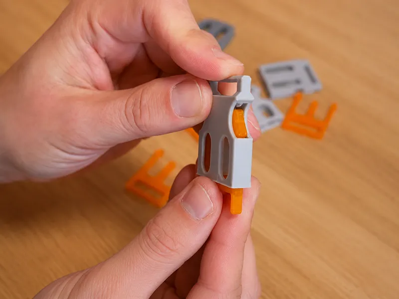
- 3D Printing (Additive): Excellent for prototyping snap fits and for low-volume parts. Designers can quickly iterate shapes and test assembly. Guides on 3D printed snap-fit enclosures also emphasize that material choice, geometry, and print orientation affect snap-fit performance. However, material and orientation matter greatly: tough, flexible polymers like Nylon 12 or flexible resins are best. Print snap arms so the layer lines run along the bending direction to avoid delamination. Leave a bit more clearance (around 0.1–0.3 mm) to compensate for printer tolerances. Keep in mind that 3D printed snaps may have weaker fatigue life than molded parts, so they are primarily for evaluation.
- CNC machining: Machined plastic prototypes (e.g. Delrin, Nylon, PC) can be used for design validation. CNC allows using engineering plastics with well-known properties. When machining snaps, account for tool geometry: avoid sharp internal corners that end mills can’t make. Include relief cuts behind snap undercuts for tool access. Very thin snap arms may need special support or may not be machinable at all. In summary, CNC is useful for one-off or small batches but requires design tweaks for tool access.
- Urethane Casting (Vacuum Casting): For short production runs (e.g. <100 pcs) or validation of snap features, urethane casting can simulate injection-molded plastic. A master mold (often silicone) produces parts in a material with similar properties. This lets engineers test assembly and feel in near-final materials without the cost of injection tooling. The downside is the cast material may not perfectly match final resin shrinkage or toughness, but it is a valuable bridge between prototypes and production.
Each manufacturing method has pros and cons. Injection molding is best for mass production, whereas 3D printing and CNC are invaluable for rapid prototyping. Whatever the process, ensure that design allowances (like draft for molding or tool radii for machining) are included.
Snap Fit Joints vs Screws, Adhesives, and Welding
| Joining Method | Advantages | Limitations | Best Use Cases |
|---|---|---|---|
| Snap Fit Joints | Fast, tool-free assembly; no extra parts (cost-effective); clean appearance; easy automation. | Limited strength (not for heavy loads); polymer fatigue/creep; sensitive to tolerances and environment. | Consumer electronics, plastic enclosures, battery covers, toys, quick-assembly fixtures. |
| Screws/Bolts | Strong, durable joints; easily removable and adjustable; can clamp multiple parts. | Slower assembly; adds part count and fastener costs; visible holes. | Structural connections, heavy loads, parts needing frequent service. |
| Adhesives (Glue) | Provides a seamless, often airtight bond; good for irregular joints. | Permanent (not easily disassembled); long cure times; joint strength depends on surface prep. | Sealed housings, repairs, permanent assemblies, non-plastic materials. |
| Welding (Plastic) | Extremely strong and permanent join; no additional hardware; can seal fluids. | Requires specialized equipment (ultrasonic, hot plate); irreversible; only for thermoplastics. | Rigid plastic enclosures requiring hermetic seals (e.g. LCD screens, medical casings). |
Snap fits excel when quick assembly and no hardware are priorities. They are cheaper in assembly than screws or rivets. However, for very high loads or safety-critical joints, traditional fasteners or welded bonds are more reliable. Xometry notes that snap fits “may fail under heavy loads”, so in automotive suspension or engine parts, mechanical fasteners are used instead. Similarly, snap joints usually can’t replace a weld or adhesive if a permanent airtight seal is required. Often, designers combine snap fits with other methods: for example, most plastic housings use snaps for alignment and a few screws to reinforce critical areas.
Applications of Snap Fit Joints
Snap-fit joints are ubiquitous in plastic products and assemblies. Typical uses include:
- Consumer Electronics: Battery covers, phone/tablet bezels, laptop access panels, remote control cases. (E.g. many gadgets have snap-on backs and compartments.)
- Automotive Interiors: Dashboard panels, light covers, trim pieces, sun visor clips. These parts often use multiple snap tabs for quick assembly of interior modules.
- Medical Devices: Plastic casings for instruments, connectors, and service panels. Snap fits allow tool-free opening of service covers.
- Household Appliances: Component housings (toasters, coffee makers), filter/cutout covers.
- Toys and Hobby Items: Toy joints, enclosures, battery hatches. Ball-and-socket snap fits are common in articulated toys.
- Packaging: Reusable lids and caps (e.g. water bottle lids, boxes) often use annular or cantilever snaps for reclosable seals.
- Clips and Fasteners: Cable clips, panel retainers, mounting brackets.
- Industrial Equipment: Guards and panels where frequent access is needed.
In general, snap fits are chosen wherever a clean appearance and fast assembly are important. For instance, many smartphone cases use plastic tabs instead of screws (though usually supplemented by a few screws) because it reduces assembly cost and yields a sleek look. Automotive trim panels rely heavily on plastic snaps to simplify production. Even in aerospace or heavy equipment, you may find snap-in fixtures and covers (though usually backed up by screws for safety).
Advantages of Snap Fit Joints
- No Extra Fasteners: Eliminates the need for screws, nuts, or rivets. This lowers part count and reduces supply chain costs.
- Fast, Tool-Free Assembly: Snap fits enable very quick assembly (and disassembly, if designed to do so). They greatly reduce labor time. Xometry notes that snap-fits allow automated assembly lines because no manual torquing is needed.
- Cost-Effective: By integrating the fastening feature into the molded part, snap fits save on additional materials and hardware. RapidDirect specifically highlights that snap-fits “save time and money by reducing material costs and part quantities”.
- Clean Appearance: No visible screws or holes improve aesthetics. Parts can have smooth surfaces.
- Lightweight: Eliminating metal fasteners can reduce weight. (Important in consumer devices or automotive applications.)
- Reusability: Some snap fits can be opened and closed multiple times without damage, facilitating maintenance or battery replacement.
- Part Consolidation: Enables complex multi-part assemblies to be simplified into fewer pieces.
- Flexibility in Design: Snap features can be molded anywhere in a part (including hidden locations), offering designers freedom to create ergonomic or sealed designs.
Overall, snap-fit joints offer a versatile, low-cost fastening method for many plastic assemblies.
Limitations of Snap Fit Joints
- Load Limitations: Snap-fit joints rely on plastic deformation, so they are not as strong as metal fasteners. They are generally unsuitable for very high loads or critical structural joints. Under heavy load or impact, a snap feature can deform or break (Xometry notes they “may fail under heavy loads”).
- Fatigue and Creep: Plastic parts under constant load or repeated cycling can creep (slowly deform) or fatigue. Stress concentrations (especially at sharp roots) accelerate this. As RapidDirect warns, “stress concentration may cause the plastic to creep, leading to a loss of pretension over time”. Repeated snap/un-snap cycles can fatigue the material at much lower stresses than its static strength.
- Precision Required: Snap fits need tight manufacturing tolerances. Too much clearance results in a loose, rattling joint; too little clearance makes assembly difficult or impossible. Small variations in mold tooling, shrinkage or part warpage can significantly affect snap performance.
- Material Sensitivity: Brittle plastics (or those that harden over time) are poor choices. Materials like filled resins or glass-filled nylon may crack. Also, environmental factors (UV, heat, chemicals) can embrittle or soften plastics, altering snap behavior.
- Complex Mold Tooling: Deep undercuts and complex snap geometries often require side-actions or collapsible cores in the mold, increasing tooling cost and cycle time. Some snap designs cannot be molded economically.
- Limited Adjustability: Once molded, the snap feature’s dimensions are fixed. If parts shrink more than expected or there’s an error, it often requires a costly mold revision to fix.
- Disassembly Issues: Permanent snap designs are not serviceable. Even “releaseable” snaps may require special tools or risk part damage if not operated correctly.
In summary, while snap fits add convenience and speed, they come with trade-offs. Engineers must ensure the snap can handle the required service conditions without failure.
Testing and Inspection for Snap Fit Joints
Quality control of snap fits focuses on ensuring reliable assembly and long-term performance:
- Assembly (Insertion) Force Test: Measure the peak force needed to snap the parts together. This should be within ergonomic or machine limits. A force gauge or tensile tester is often used.
- Retention (Pull-off) Force Test: Measure the force required to pull the parts apart. This verifies the snap’s holding strength. Use a pull-test fixture or similar.
- Cycle Testing: For reusable snaps, repeatedly assemble/disassemble hundreds or thousands of times to simulate lifetime use. Check for signs of fatigue, cracking, or force reduction.
- Dimensional Inspection: Use calipers, micrometers, or CMM to verify critical snap dimensions (arm thickness, hook depth, clearances) meet specification. Features like the root radius, lead-in chamfer, and groove depth are checked.
- Surface and Material Check: Inspect for surface defects (burrs, sink marks, weld lines) that could weaken the snap. Check for whitening or micro-cracks after assembly (an indicator of overstress).
- Functional Fit Check: Physically assemble the parts to ensure smooth engagement and a secure “click.” Check for unwanted play or misalignment.
- Environmental Testing: If needed, test the assembled parts under the expected service conditions (temperature, humidity, UV) to see if the snap loosens or deforms.
- Documentation: Record all inspection results and ensure any failures trigger a design or process review.
Thorough testing is especially important for snaps used in critical or safety-related applications. Catching a design flaw early (e.g. a crack in the first prototype) saves costly rework of production tooling.
Cost Considerations for Snap Fit Joints
- Part and Hardware Cost: Snap fits eliminate fasteners, saving on purchased parts. This reduces the BOM cost compared to screws, springs, or clips.
- Tooling Cost: Complex snap features (deep undercuts, multiple slides) raise injection mold cost. A simple straight cantilever costs little, but a concentric annular snap often needs sliding cores.
- Machining/Prototyping Cost: CNC machining or 3D printing of prototypes is relatively low-volume and adds per-part cost, but speeds up design.
- Production Time: Snap assemblies can be faster to assemble than screwed assemblies, reducing labor cost. (However, cycle time in molding may increase if the part has many undercuts.)
- Tolerance and Quality Control: Tighter tolerances (for proper fit) increase inspection time and possible scrap. Parts outside tolerance may be unusable.
- Secondary Operations: Sometimes snaps require post-processing (deburring the hooks, or separate fixturing). Any extra steps add cost.
- Design Iteration: Because snap fits often need iterative design, the engineering cost to prototype and test multiple versions should be considered.
- Quantity: Snap fits shine in moderate to high volumes (where tooling can amortize). In very low volumes, simpler fastening might be cheaper overall.
In short, the economic value of a snap-fit joint comes from eliminating parts and speeding assembly. But this must be balanced against any increased design, molding, and manufacturing cost. A wise approach is to prototype and analyze the snap early, to avoid expensive mold revisions later.

How to Choose the Right Snap Fit Joint
Select the snap-fit type based on geometry and requirements:
- General Flat Assemblies: Cantilever or U-shaped snaps are usually ideal. Use cantilever snaps for single-panel covers; U-shaped if you need stronger grip.
- Round/Cylindrical Parts: Annular snaps work best (e.g. bottle caps, tube fittings). They provide uniform 360° locking.
- Hinged/Latching Parts: Torsion snaps or L-shaped (a cantilever turned sideways) are suited for lids and latches that open with a twist.
- Multi-Axis Movement: Ball-and-socket snaps allow rotation after assembly (good for adjustable joints or quick-disconnect fittings).
- High Strength/Load: If the part sees heavy load or critical service, consider adding threaded inserts or fasteners instead of relying solely on a plastic snap (see Xometry’s guidance in such cases).
- Ease of Manufacture: If your design can avoid complex undercuts, simpler cantilever snaps are easier (and cheaper) to mold. For example, [25] notes cantilever snaps are best for low-to-moderate loads, whereas annular snaps (with higher load distribution) require more precise molding.
- Space Constraints: If limited space is available, a U-shaped snap may give required compliance where a single thick arm cannot fit.
- Material Choice: Choose the material first. For a given material, you may need to adjust geometry (e.g. larger radii in brittle plastics).
- Assembly Direction: Ensure the snap can be deflected in the intended assembly direction without interference.
Use prototyping and DFM analysis to validate your choice. For example, Fictiv’s guide recommends following injection molding best practices (draft, fillets, etc.) to ensure manufacturability. The best snap fit is one that meets the application’s needs accurately and consistently while keeping production practical and cost-effective.
Conclusion
Snap-fit joints are integrated fastening features that join parts by elastic deformation, eliminating separate screws or glue. The primary snap-fit types – cantilever, annular, torsional, U-shaped, and ball-and-socket – each serve different purposes in product design. In designing them, engineers balance material properties, part geometry, and assembly forces to ensure the feature locks securely without over-stressing the material. When done right, snap fits dramatically reduce assembly time and cost by integrating the latch mechanism into the part. However, they come with trade-offs (limited load capacity, fatigue concerns, tight tolerances) that must be managed through careful design and testing. In product development, the key is early DFM review and prototyping: test-fit and cycle-test your snap fits before committing to tooling. As Xometry emphasizes, snap-fits “provide a versatile, cost-effective solution” for plastic parts in molding or 3D printing, as long as the snap-fit type, material, and stress factors are properly addressed. In summary, successful snap-fit design yields reliable, serviceable joints with fewer parts and faster assembly, which can give your product a competitive edge in manufacturing efficiency.
FAQ About Snap Fit Joints
What are snap fit joints?
Snap fit joints are fastening features built into parts (usually plastics) that lock together through elastic deformation. One part has a flexible protrusion (hook or tab) that bends during assembly and snaps into a mating undercut in the other part. This holds the parts together without screws, rivets, or adhesives.
What are the main types of snap fit joints?
The most common types are cantilever (single flexible tab), annular/circular (ring-shaped lip), torsional (twisting arm), U-shaped (double-arm), and ball-and-socket (spherical joint). Each serves different shapes and uses. For example, cantilevers are simple and widely used; annular snaps work for round caps; torsion snaps are good for latches; ball-and-socket allow hinged movement.
What materials are best for snap fit joints?
Plastics with high flexibility and fatigue resistance are preferred. Common choices include polypropylene (PP), polycarbonate (PC), nylon (PA), ABS, and acetals (POM). These materials can flex repeatedly without cracking. Metals (e.g. spring steel) can be used in high-stress or high-temperature applications, but most snap fits are designed in thermoplastics.
Are snap fit joints permanent?
It depends on the design. Some snap fits are intended to be permanent (one-time assembly), while others are designed to be reusable. The distinction lies in the hook geometry and angles. A shallower hook with a release ramp can allow disassembly, whereas a steep hook will hold permanently. As RapidDirect notes, “the design determines if the connection will be permanent or temporary”.
Why do snap fit joints fail?
Common failure causes include excessive stress or fatigue. Sharp corners or very stiff materials can cause cracking at the snap arm base. Repeated assembly cycles can also lead to fatigue fractures well below the material’s rated strength. Other issues are improper tolerances (leading to too much play or too high insertion force), overly large deflection, or creep in the plastic over time. Good design and material choice mitigate these failures.
Can snap fit joints be 3D printed?
Yes, 3D printing is often used to prototype snap-fit parts. Fictiv points out that CNC and 3D printing “open up new opportunities” for snap-fit design. However, printed snaps require careful consideration: use flexible, tough materials (e.g. Nylon12 or flexible resin) and orient the print so that layer lines run parallel to the flexing direction. Keep extra clearance for print tolerances. 3D-printed snaps can function for testing, but final production snaps are usually molded for best performance.