
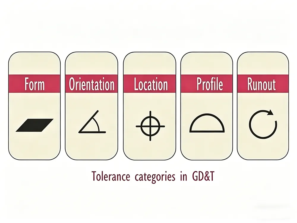
If you’ve ever opened an engineering drawing and felt overwhelmed by symbols, frames, and annotations, you’re not alone. Many engineers first encounter GD&T symbols, GD and T symbols, or complex symbol GD and T blueprint annotations used in CNC machining services and find them difficult to interpret.
But in real manufacturing environments, GD&T isn’t there to make things complicated. It’s there to make things clearer. It tells everyone involved—designers, machinists, inspectors—exactly what matters and what doesn’t.
What Are GD&T Symbols
GD&T stands for Geometric Dimensioning and Tolerancing, as explained in this overview of GD&T fundamentals.It’s a standardized system used to define how much variation is allowed in the geometry of a part, and GD&T tolerancing symbols are the core language used to communicate these requirements.
Traditional dimensioning might tell you a hole is 10 mm in diameter. GD&T goes further—it defines how straight, how round, how aligned, and how precisely located that hole must be.
In other words, GD&T controls not just size, but shape and relationship.
GD&T symbols, sometimes also referred to as GD and T symbols, are the visual language of this system. Instead of long notes or explanations, engineers use standardized symbols to communicate requirements clearly and efficiently.
The Role of GD&T Symbols in Engineering Drawings
On a drawing, GD&T symbols are usually placed inside feature control frames. In many cases, these are also described as symbol GD and T blueprint annotations because they define how features should behave in real manufacturing.
These frames specify:
- What kind of control is required
- How much variation is allowed
- Which reference surfaces (datums) are involved
This allows a drawing to communicate functional requirements without ambiguity.
Common GD&T Symbols and Their Meanings
Here’s a practical overview of commonly used GD&T symbols, often summarized in a GD&T symbols chart for quick reference in engineering work:
| Symbol | Name | Meaning | Application |
|---|---|---|---|
| ⏥ | Flatness | Controls surface flatness | Sealing surfaces |
| ⌖ | Position | Controls feature location | Hole alignment |
| ∥ | Parallelism | Maintains parallel orientation | Sliding parts |
| ⟂ | Perpendicularity | Ensures 90° relationship | Mounting features |
| ↻ | Runout | Controls rotation accuracy | Shafts |
| ⌯ | Profile | Controls complex shapes | Curved surfaces |
Understanding a GD&T symbols chart is often the fastest way for beginners to get familiar with different tolerancing requirements.
How to Read GD&T Symbols on Engineering Drawings
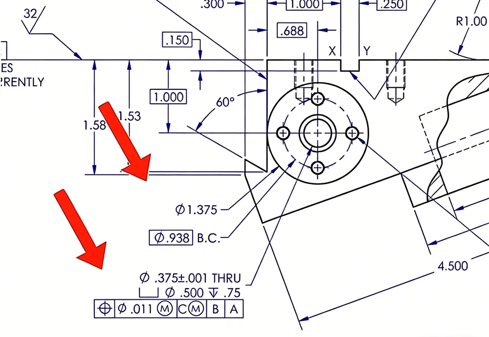
Reading GD&T becomes much easier once you follow a process, as outlined in GD&T engineering standards and practices. When looking at GD&T symbols or GD and T symbols on a blueprint, it helps to break things down step by step.
Step 1: Identify the feature control frame
Step 2: Look at the symbol
Step 3: Check the tolerance value
Step 4: Identify the datum references
This structured approach makes it easier to interpret even complex GD&T tolerancing symbols in real engineering drawings.
GD&T Symbols vs Traditional Dimensioning
Traditional dimensioning focuses on size, while GD&T focuses on function. This is one of the main reasons GD&T symbols are widely used in modern engineering drawings instead of relying only on basic dimensions.
With traditional methods, drawings can be ambiguous. With GD&T tolerancing symbols, requirements become precise and standardized.
Applications of GD&T in Real-World Scenarios
GD&T symbols are used across many real-world scenarios, not just in large industries but also in everyday engineering drawings and digital design workflows.
GD&T in Engineering Drawings
This is the most common application. GD&T symbols define how a part should be manufactured and inspected, often appearing as symbol GD and T blueprint annotations that guide production teams.
GD&T in CNC Machined Parts
In CNC machining, GD&T symbols help define how parts should be positioned, machined, and inspected. Without GD&T tolerancing symbols, achieving consistent results would be much more difficult.
GD&T in 3D Printing
In additive manufacturing, GD&T is becoming more important. Designers still rely on GD&T symbols to control critical features, even when parts are produced layer by layer.
GD&T in Inspection and Quality Control
Inspection teams often rely on GD&T symbols chart references to verify whether a part meets its requirements. Tools like CMM machines use these tolerances to check part accuracy.
FAQ
What are GD&T symbols used for
GD&T symbols and GD and T symbols are used to define allowable variation in CNC machining tolerances.
What is the most common GD&T symbol
Position is one of the most widely used GD&T tolerancing symbols.
How do you read GD&T symbols
By analyzing the feature control frame, tolerance, and datum references shown on the blueprint.

