
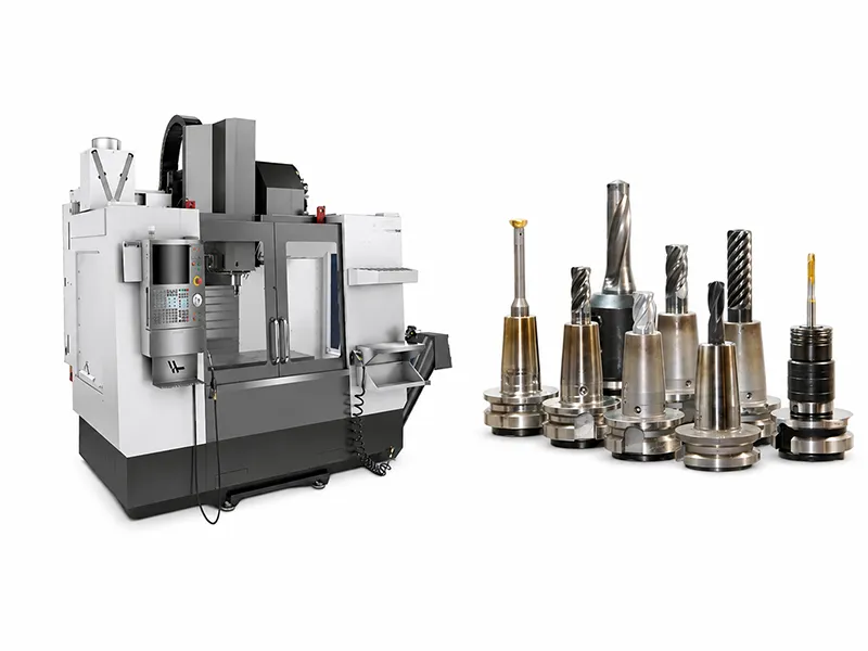
Milling operations use rotating cutting tools to remove material from a workpiece and create flat faces, slots, pockets, contours, threads, and complex surfaces. In CNC machining, choosing the right operation directly affects accuracy, surface finish, tool life, cycle time, fixturing complexity, and total cost. This guide explains twelve common milling operations, how each one is used, where they overlap, and how to choose the best process for custom CNC parts.
What Milling Operations Are and How CNC Milling Works
Milling is a subtractive manufacturing process in which a rotating cutter removes material from a workpiece that is typically clamped and held stationary. In CNC milling, the machine controls tool motion along multiple axes to create flat surfaces, pockets, slots, contours, holes, and threads. In practical terms, a milling operation is chosen according to the feature being produced: a flat face, a side wall, a slot, a cavity, a profile, a thread, or a three-dimensional surface.
A modern CNC milling workflow usually starts with a CAD model or engineering drawing, then moves into CAM setup, toolpath creation, workholding definition, roughing and finishing operations, post-processing, and inspection. Autodesk’s manufacturing setup guidance explicitly defines setup creation around the machine, work coordinate system, model, stock, and post-processing, while its CNC milling training materials frame roughing, finishing, documentation, and inspection as core steps in the machining process.
A useful way to think about the workflow is: CAD model or drawing → CAM setup → tool selection and toolpaths → workholding and zeroing → milling → inspection. That sequence is especially important for CNC milling services because operation choice is not only a programming decision; it also affects tooling access, setup count, and inspection strategy.
Quick Comparison of Common Milling Operations
| Milling operation | Main purpose | Typical part features | Common tool |
|---|---|---|---|
| Face milling | Produce broad flat faces | Mounting surfaces, datum faces, plates | Face mill |
| Plain milling | Machine broad flats parallel to cutter axis | Large slabbed surfaces | Plain or slab mill |
| End milling | General-purpose cutting of surfaces and features | Steps, pockets, slots, profiles | End mill |
| Side milling | Machine side walls and shoulders | Vertical walls, shoulders, side grooves | Side-and-face cutter or end mill |
| Slot milling | Cut narrow openings and channels | Keyways, channels, T-slots, openings | Slot cutter or end mill |
| Angular milling | Machine inclined features | Bevels, chamfers, V-grooves, dovetails | Angle cutter or end mill |
| Form milling | Reproduce a specific profile | Radii, beads, formed grooves | Form cutter |
| Straddle milling | Machine parallel sides in one setup | Opposite flats, splines, hex forms | Paired side cutters |
| Gang milling | Machine multiple features in one pass | Repetitive production features | Multiple cutters on one arbor |
| Profile milling | Machine external or internal contours | Outlines, curved edges, 3D contours | End mill or ball nose mill |
| Pocket milling | Remove material inside a bounded area | Cavities, recesses, housings | End mill |
| Thread milling | Produce internal or external threads | Threaded holes and bosses | Thread mill |
This comparison table synthesizes traditional milling classifications with modern CNC feature-based operations. Traditional terms such as plain, angular, form, straddle, and gang milling still matter, but in day-to-day CNC work they often overlap with CAM toolpaths such as contouring, pocketing, and thread milling.
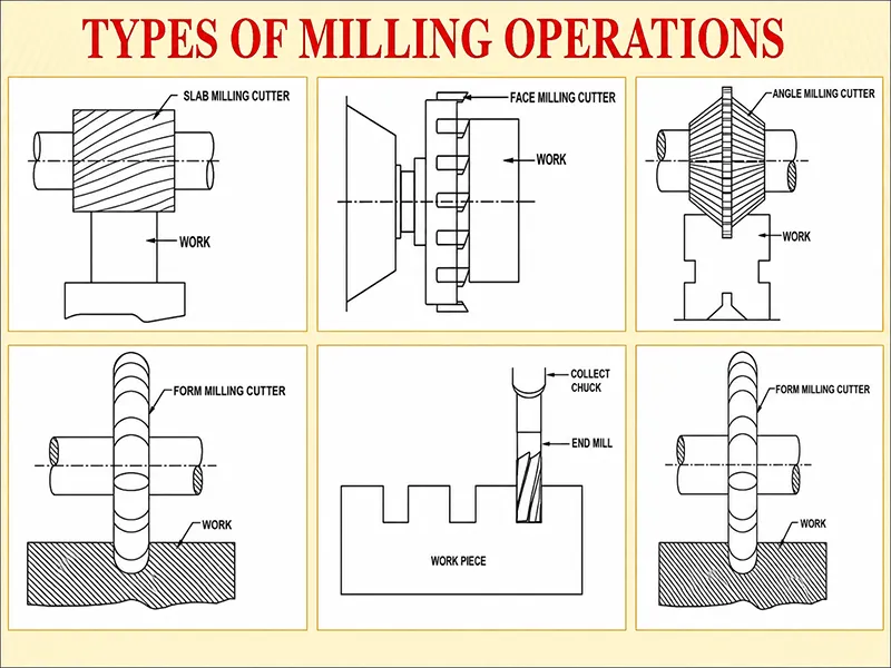
Face, Plain, End, Side, Slot, and Angular Milling
Face milling
is used to level and smooth broad surfaces perpendicular to the spindle axis. Sandvik calls it the most common milling operation, and Kennametal notes that it is often one of the first operations on a part because it creates a flat top surface and establishes a reference datum for later machining. That makes face milling especially important for base plates, fixture surfaces, aluminum blocks, and steel plates that need a reliable mounting or measurement face.
Plain milling
often called slab milling in traditional machining language, machines flat surfaces with the cutter axis parallel to the surface being cut. In older horizontal-machine terminology, it is the classic way to machine wide flats using the cutter periphery rather than the cutter face. In modern CNC shops, some work that was once labeled plain milling is now handled by face milling or end milling depending on machine orientation, tool access, and surface requirements.
End milling
is the most flexible of the common CNC milling operations. Kennametal describes end mills as rotating tools used to remove material from a workpiece, while Autodesk shows that flat end mills are efficient for quickly clearing flat surfaces and that ball nose mills are better for curved surfaces and finishing. In practice, end milling covers steps, shoulders, slots, shallow pockets, external profiles, and many mixed-feature parts in aluminum, steel, stainless steel, plastics, and composites.
Side milling
is often discussed today under the broader category of shoulder milling or side-and-face milling. Sandvik’s shoulder milling guidance centers on achieving true ninety-degree shoulders and notes that square shoulder cutters, end mills, long-edge cutters, and side-and-face cutters may all be used. This is the operation family you choose for upright side walls, shoulders, stepped geometry, and narrow side features where wall straightness and cutter rigidity matter.
Slot milling
is used for open or closed slots, keyways, channels, and similar long narrow openings. Sandvik notes that slot or groove milling can involve short or long, open or closed, straight or non-straight slots, and that tool choice depends mainly on groove width and depth. The same guidance also notes that end mills are selected for shorter and shallower slots, especially closed grooves and keyways, while heavier slotting may call for long-edge or side-and-face cutters.
Angular milling
machines surfaces that are neither parallel nor perpendicular to the cutter axis. Smithy’s machining reference describes it as the standard choice for angled features such as chamfers, serrations, grooves, and dovetails, traditionally done with single-angle or double-angle cutters. In CNC machining, the same feature may also be created by an end mill with programmed multi-axis positioning or 3+2 machining when the part or tool is locked at a specific angle.
Form, Straddle, Gang, Profile, Pocket, and Thread Milling
Form milling
uses a cutter whose profile is shaped to match the feature being machined. Smithy describes form milling as producing contours composed of curves and straight lines, or entirely of curves, in a single cut. That makes it attractive for repeated radii, beads, concave or convex features, and other recurring shapes where profile repeatability matters more than tool flexibility.
Straddle milling
machines two or more parallel vertical surfaces at the same time by mounting two side milling cutters on the same arbor with controlled spacing. Smithy notes that this arrangement lets two sides of the workpiece be machined simultaneously while controlling final width accurately. It is especially useful for opposite flats, hex forms, splines, and other parts where matched parallel sides are more important than freeform flexibility.
Gang milling
mounts two or more cutters on the same arbor so that several features can be produced in one pass. Smithy defines gang milling in exactly those terms, and Sandvik’s CoroMill 331 application data still lists gang milling among its industrial use cases. In practical CNC terms, gang milling is most attractive for repetitive production work because it trades more complex setup for shorter cycle times and consistent multi-feature spacing.
Profile milling
machines external or internal contours by following a defined path. Sandvik describes profile milling as a common operation in which round inserts are often used for roughing and semi-roughing, while ball nose end mills are used for finishing and super-finishing. Autodesk’s contour toolpath reference likewise defines 2D contour as the CAM operation used to machine profiles, typically as a finishing strategy, while Sandvik notes that true three-dimensional profile work may require four- or five-axis capability rather than only three-axis motion.
Pocket milling
removes material inside a bounded region to create cavities, recesses, and enclosed internal spaces. Autodesk’s 2D Pocket reference defines it as a roughing operation with an optional finish pass for clearing a cavity, an open pocket, or the area around a boss. Its 3D Pocket Clearing reference describes a pocketing-style strategy for removing large areas of material, and Autodesk’s adaptive and pocket references both show how rest machining limits the next pass to material that the previous tool could not remove.
Thread milling
creates internal or external threads by moving a rotating thread mill along a helical toolpath. Autodesk’s thread strategy supports straight or tapered walls, internal or external circular faces, and single- or multi-lead threads. Sandvik explains that the pitch is generated by the tool’s circular ramping movement, while According to Haas thread milling guidance, one thread mill of the same pitch can machine multiple thread sizes, support fit adjustments through cutter compensation, and reduce the risk associated with a broken tap in an expensive part.
Materials, Tolerances, and Cutting Strategy
The same milling operation can behave very differently depending on the material. Sandvik’s material guidance shows that steel, stainless steel, cast iron, non-ferrous alloys, titanium, and heat-resistant superalloys each present different machinability issues, from burr formation and built-up edge to thermal cracks, abrasive wear, and poor heat handling. For aluminum and other non-ferrous alloys, Sandvik emphasizes sharp, polished cutting edges, coolant use, and chip evacuation, while Harvey Tool’s plastics guidance highlights sharp edges and large flute openings for cleaner plastic cutting.
That is why the “best” milling operation is never chosen by geometry alone. Haas notes that softer materials such as aluminum often benefit from sharper tools and fewer flutes, while harder materials need more robust tooling and coatings. Sandvik likewise shows that titanium and HRSA demand rigid machines, controlled cutting forces, and tools that can handle heat concentration and edge chipping.
Accuracy and surface finish depend on more than the operation name. Tool deflection, stickout, spindle condition, cutter engagement, step-over, and feedrate all matter. Harvey warns that excessive tool deflection shows up as poor surface finish, dimensional inaccuracy, and tool damage, while Haas notes that spindle taper condition directly affects cutting accuracy and surface finish. Autodesk’s manufacturing design guidance adds that deep pockets, large step-downs, and high feedrates all increase side loading and therefore deflection risk.
For that reason, most CNC milling operations are planned in stages rather than as a single pass. Autodesk’s milling-tool explanation distinguishes flat end mills for fast roughing from ball nose tools for finishing curved surfaces, and its CAM training materials explicitly organize 3-axis work around roughing and finishing operations. On pocketing and contour operations, Autodesk also provides finish-pass and rest-machining options, which is exactly how many shops stabilize size and improve wall and floor quality on custom CNC parts.
When tolerances become tight, secondary operations may still be the right answer. Autodesk’s manufacturing-for-design guidance notes that hole size may be altered after drilling by later operations such as reaming, and Haas describes fine boring systems as a route to precise, tight-tolerance holes. In other words, a milled part may combine face milling, pocket milling, profile milling, and thread milling, but only a few critical features may justify extra finishing passes, boring, reaming, or expanded inspection.
As for climb milling and conventional milling, modern CNC practice usually favors climb milling. Harvey states that climb milling generally reduces load on the cutting edge, leaves a better surface finish, improves tool life, and lowers chip recutting compared with conventional milling. Still, the same source also notes that conventional milling remains relevant when backlash is not properly controlled or when cutting certain cast, forged, or hard-skinned surfaces.
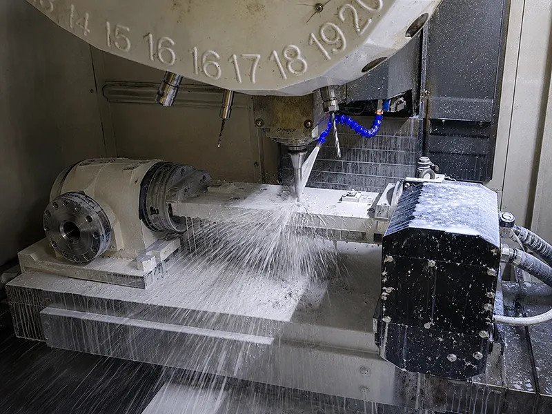
Choosing the Right Operation for the Part
| Part feature or requirement | Usually the best starting operation |
|---|---|
| Large flat mounting face | Face milling |
| Broad flat surface parallel to cutter axis | Plain milling |
| Mixed features such as steps, shoulders, and shallow pockets | End milling |
| Straight side wall or shoulder | Side milling |
| Keyway, narrow opening, or channel | Slot milling |
| Bevel, chamfer, or V-groove | Angular milling |
| Repeated special contour | Form milling |
| Two parallel sides in one setup | Straddle milling |
| Several repeated features in one pass | Gang milling |
| External outline or curved contour | Profile milling |
| Enclosed cavity or recess | Pocket milling |
| Internal or external thread | Thread milling |
This selection matrix is a practical starting point, not a rigid rule. Real parts often combine several operations in one setup plan, and the final decision depends on feature geometry, material, tolerance, required surface finish, tool access, axis capability, quantity, and inspection needs. In custom CNC machining, the most efficient route is the one that produces the required feature reliably with the fewest unnecessary setups and the least tool or fixturing risk.
That is also why traditional names and CAM toolpath names sometimes overlap. For example, a programmer may describe a job as end milling from the cutter point of view, 2D contouring from the CAM point of view, and profile milling from the feature point of view. Those labels are not contradictory; they simply describe the same cut from different manufacturing angles.
Design, Cost, Supplier Selection, Conclusion
Design for milling starts with tool access and rigidity. Autodesk’s manufacturing design guidance recommends keeping internal radii larger than the available tool radius, avoiding unnecessarily deep pockets, and reducing setup count wherever possible. The same guidance shows that deep pockets, thin ribs, and high-aspect-ratio tooling increase deflection and vibration risk, and it notes that if feature height grows too large relative to feature width, surface finish and dimensional stability quickly suffer.
A good CNC-milled part design therefore uses standard tool-accessible radii, reasonable slot depths, practical pocket depths, and clear identification of truly critical surfaces. Autodesk also advises that selecting larger internal fillets can allow the use of larger, stiffer tools, while reducing the number of setups lowers production time and often improves consistency. Those are classic design-for-manufacturing choices because they reduce tool changes, machining time, vibration risk, and the need for secondary work.
Cost follows the same logic. Material choice matters, but setup count, pocket depth, contour complexity, required finish quality, thread features, inspection requirements, and secondary finishing can matter just as much. Autodesk’s manufacturing guidance notes that complex surfaces often need smaller tools and more passes, which increases machining time, while every additional setup adds time and may require more fixturing. A practical quoting model is therefore: material + setup time + cutting time + tooling wear + finishing + inspection. That formula is a planning heuristic, but it matches the cost drivers documented in Autodesk’s machining and inspection guidance.
In practice, a strong CNC milling supplier should be able to discuss more than spindle horsepower or machine size. The better question is whether the supplier can set up the part correctly, choose the right milling operations, control roughing and finishing, manage fixturing and datum strategy, and verify critical features through probing or inspection. That is an inference drawn directly from Autodesk’s setup, CAM, and inspection guidance, which treats setup definition, process planning, workholding, and inspection as core parts of successful CNC milling.
Taken together, the twelve common milling operations in this guide cover most of the feature families seen in CNC machining: flat faces, broad slabs, shoulders, slots, angles, formed contours, parallel sides, repeated multi-feature passes, external profiles, enclosed pockets, and threads. The right choice is not the one with the most familiar name, but the one that fits the part’s geometry, material, tolerance target, surface-finish requirement, setup strategy, and production volume. For custom CNC parts, the best milling operation is the one that produces the required feature accurately, efficiently, and consistently while keeping machining cost under control.
FAQ About Types of Milling
What are milling operations?
Milling operations are machining processes in which a rotating cutting tool removes material from a clamped workpiece to create surfaces, slots, pockets, contours, threads, and other part features. In CNC machining, the term usually refers to the feature-specific cutting strategy selected in CAM and executed on the machine.
What are the most common types of milling operations?
The most commonly discussed types are face milling, plain milling, end milling, side milling, slot milling, angular milling, form milling, straddle milling, gang milling, profile milling, pocket milling, and thread milling. Some are traditional classifications, while others map directly to common CAM toolpaths used in modern CNC milling.
What is the difference between face milling and end milling?
Face milling is primarily used for broad flat surfaces perpendicular to the spindle and is often used to establish reference faces. End milling is more flexible: it can machine flats, steps, shoulders, slots, pockets, and contours using both the end and side cutting edges of the tool.
Which milling operation is used for pockets?
Pocket milling is the standard operation for removing material inside a bounded area to create cavities and recesses. In CAM, this usually begins with a roughing strategy and may include finish passes and rest machining so that smaller tools only remove material left behind by earlier passes.
Which milling operation is best for CNC machined parts?
There is no single best operation for every CNC machined part. The right choice depends on the feature being made, the material, the tolerance and finish required, the available tool access, the number of setups, and the production volume. Many successful parts use several milling operations in the same process plan.

