
Gears are one of the most essential components in mechanical transmission systems, used to transfer motion, control speed, and increase torque in everything from industrial machinery to automotive systems. Understanding the types of gears is important for engineers, designers, and manufacturers because each gear type is built for specific shaft arrangements, load conditions, and performance requirements. In real applications, choosing between the different types of gears can affect efficiency, noise level, durability, and overall machine design. This guide explains the classification, uses, and key design tips for common gear types, helping you select the right option for your application.
What Are Gears?
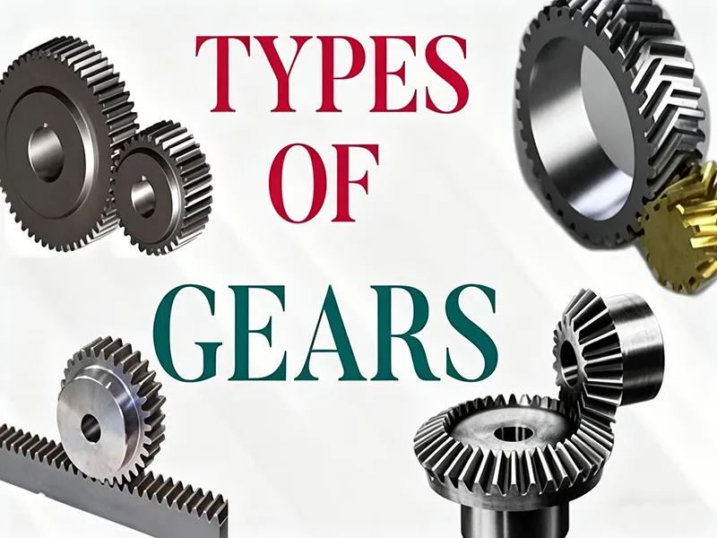
Gears are toothed wheels that mesh with each other to transmit power between shafts. They consist of circular wheels with evenly spaced teeth on the rim; when two gears mesh, rotation and torque are transferred without slippage. This interlocking action allows gears to change speed, torque, and direction of motion – for example, a small pinion (few teeth) driving a larger gear increases torque while reducing speed, or vice versa. Gears are ubiquitous in machinery because they provide precise, efficient motion transfer in mechanical systems, making them critical components in vehicles, industrial equipment, clocks, and many other devices.
Types of Gears and How They Are Classified
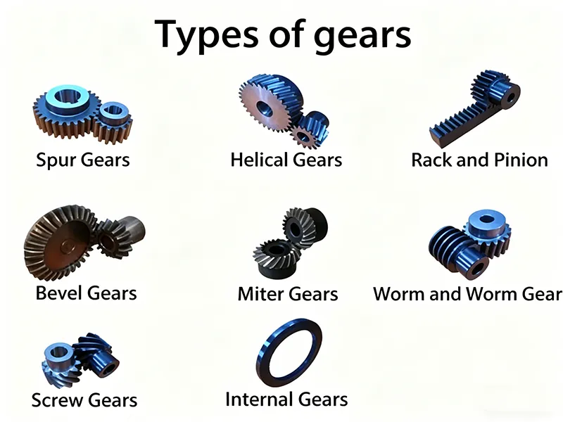
Gears can be classified in several ways, as shown in this gear classification reference. One common scheme is by shaft orientation: parallel (axes aligned), intersecting (axes meet), and skewed (neither parallel nor intersecting). For example, spur and helical gears operate on parallel shafts, bevel gears on intersecting shafts (usually 90°), and worm or hypoid gears on non-parallel shafts. Another classification is by tooth geometry: straight (spur), angled (helical), or curved (spiral/bevel) teeth. This affects how smoothly gears mesh – angled or curved teeth engage gradually (lower noise) compared to sudden engagement of straight teeth. Gears are also grouped by function: some increase speed or torque, while others convert rotary to linear motion (e.g. rack-and-pinion). Each classification helps engineers narrow down choices based on shaft layout, noise and load requirements, and mechanical function.
- Shaft orientation: Parallel axes (spur, helical), Intersecting axes (bevel), Skewed axes (worm, hypoid).
- Tooth geometry: Straight teeth (spur) vs angled/spiral teeth (helical, spiral bevel).
- Function: Speed increasers/reducers, torque multipliers, or motion converters (e.g. rack and pinion for rotary-to-linear).
Together, these classification criteria guide the choice of gear type in design.
Different Types of Gears Explained
Spur Gears
Spur gears have straight teeth cut parallel to the gear’s axis. They are the simplest and most common gear type. Advantages: very high efficiency (up to ~98%) and low manufacturing cost; design is simple and easy to inspect. Limitations: all teeth engage at once, so spur gears can be noisy and prone to vibration at high speed; they only handle parallel shafts and purely radial loads. Spur gears are often used in low-speed, light-load applications like clocks, simple gearboxes, conveyors, and toys.
Helical Gears
Helical gears are similar to spur gears but have teeth cut at an angle (helix) to the gear axis. This angled tooth profile causes the teeth to engage gradually, resulting in smoother and quieter operation than spur gears. Helical gears also have more teeth in contact at once, so they can carry higher loads. They are widely used in high-speed transmissions for automotive, aerospace, and industrial machinery. Disadvantages: the angled teeth generate axial thrust (sideways force), requiring bearings to absorb the force. They are also more complex and costly to manufacture, and efficiency is slightly lower than spur gears (typically ~97%).
Bevel Gears
Bevel gears have cone-shaped pitch surfaces and transmit power between intersecting shafts, most commonly at 90°. Straight-bevel gears have straight teeth, while spiral-bevel gears have curved teeth for smoother engagement. Advantages: bevel gears efficiently change the direction of motion and can reverse rotation (e.g. 90° drive) in a compact layout. They are essential in drives where shafts intersect (like car differentials). Limitations: bevel gears are more complex to design and align. Precision is critical; spiral bevels are costly to machine and require careful assembly. Common applications include differential drives in automobiles, right-angle drives in machine tools, and many industrial gearboxes.
Worm Gears
A worm gear consists of a worm (a screw-like gear) and a worm wheel (similar to a spur gear) on two non-intersecting, usually perpendicular shafts. Advantages: worm gears can achieve very high reduction ratios in a single stage (a small worm driving a large wheel), and they run quietly with smooth motion. They also offer self-locking action when the worm lead angle is small (the worm can drive the wheel, but the wheel cannot back-drive the worm), which is useful for hoisting or lifting applications. Limitations: the sliding contact between worm and wheel generates significant friction, so worm drives are less efficient (often 50–90% depending on lead angle) and produce heat. Proper lubrication and tougher materials are needed to reduce wear. Worm gears are found in conveyors, elevators, tuning mechanisms (guitar pegs), and compact speed reducers where high reduction is needed in a small package.
Rack and Pinion Gears
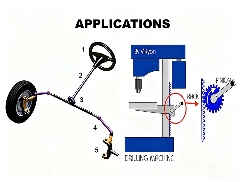
A rack-and-pinion pair consists of a circular gear (pinion) meshing with a linear toothed rack. This arrangement converts rotary motion of the pinion into linear motion of the rack (or vice versa). Features: Racks can have straight or helical teeth; helical racks engage more smoothly and quietly. This mechanism provides precise linear positioning. Applications: Steering systems in cars (the steering wheel turns a pinion that moves the rack), CNC machines, linear actuators and slides, and any system requiring direct conversion of rotation to straight-line motion.
Planetary Gears (Epicyclic)
Planetary gears (epicyclic gears) consist of a central sun gear, several planet gears mounted on a carrier, and an outer ring gear with internal teeth. The planets roll inside the ring and also mesh with the sun. This coaxial arrangement is very compact. Advantages: planetary gear sets share load among multiple planets, giving very high torque capacity and torque density in a small volume. They also allow complex gear ratios (through different connections of ring, sun, or carrier) and have good shock-load handling due to load sharing. Limitations: the arrangement is complex and requires high-precision manufacturing and assembly, making it expensive. Applications: high-performance systems like robotics, aerospace actuators, servo drives, and electric vehicle drivetrains where space is limited and high power density is needed.
Types of Gears by Shaft Arrangement

Gears can also be grouped by the relative orientation of their shafts:
- Parallel-Shaft Gears: Shafts are parallel. Typical examples are spur and helical gears which work on parallel shafts. These gears provide high efficiency and easy mounting for applications like parallel gear trains and speed reducers.
- Intersecting-Shaft Gears: Shafts intersect (usually at 90°). Bevel gears (straight, spiral, hypoid, miter) are used here. They allow efficient right-angle drives, as in differential units or offset gearboxes.
- Non-Parallel, Non-Intersecting (Skewed) Gears: Shafts are neither parallel nor intersecting. Worm gears and crossed helical (screw) gears fall into this category. These are used when shafts must cross without intersecting, enabling large speed changes or offset drives.
Key Uses of Different Types of Gears
Different industries favor certain gear types based on performance needs:
- Automotive Systems: Cars use a variety of gears. Helical gears are common in transmissions for smooth, quiet operation. Differential units use bevel or hypoid gears to transmit power at right angles. Rack-and-pinion systems are used for steering. Planetary gearsets often appear in automatic transmissions and e-axles for compact multi-stage reduction.
- Industrial Machinery: Heavy equipment (gearboxes in conveyors, mixers, etc.) often use robust helical and spur gears. Machine tools employ helical gears for main drives and bevel gears for angle-head drives. Worm and helical gears are also found in pumps, compressors, and large reduction drives.
- Robotics and Automation: Robotic arms and precision actuators require gears with high accuracy and compact size. Planetary and helical gears are common in servo motors and reducers because they provide high torque in a small package and smooth motion. Precision timing gears (small spur or internal gears) appear in instrumentation and control systems.
- Aerospace Equipment: Aircraft and spacecraft use gears where weight and precision are critical. High-strength alloy helical gears are used in control actuators and engines, and special hypoid or bevel gears may be used in auxiliary gearboxes. Planetary gearboxes are used in avionics and satellite positioning because of their compact, reliable high-ratio performance.
- Consumer and Precision Devices: Small spur or plastic gears are used in printers, clocks, and household appliances for cost-effective power transfer. Medical instruments and high-precision devices use low-backlash planetary or harmonic gears for accuracy.
- New Energy Vehicles (EVs): Electric vehicles often use planetary and hypoid gearsets in their reduction gearboxes and transfer cases. Planetary gears give high reduction ratios in a compact form, which is ideal for EV motor drives that must be lightweight and efficient. Helical gears may be used in transmission stages to handle high speeds and reduce noise.
- High-Performance Industrial Systems: In heavy-duty applications (e.g. wind turbines, mining equipment, crane drives), large helical, bevel, and planetary gearboxes are used for their durability and high torque capability. These systems demand gears that can handle massive loads and harsh conditions, often combining multiple gear types in multi-stage reductions.
Gear Design Basics
Important gear parameters include:
- Number of Teeth (N): An integer count of teeth on each gear. It determines the gear ratio (ratio of rotational speeds) and affects size and strength. For example, a 20-tooth gear driving a 40-tooth gear gives a 2:1 speed reduction.
- Module (m) / Diametral Pitch (DP): These describe tooth size. Module (metric) is pitch diameter divided by number of teeth. Diametral pitch (imperial) is teeth per inch of pitch diameter. Gears mesh correctly only if they have the same module or DP.
- Pressure Angle: The angle (commonly 20° or 14.5°) at which teeth are formed relative to the gear’s pitch circle. It affects the shape of the tooth profile and the distribution of forces. Common modern gears use a 20° pressure angle.
- Helix Angle: For helical gears, the helix angle is the angle of the tooth relative to the gear axis. Larger helix angles increase the axial thrust but spread the load over more teeth for strength and quietness.
- Backlash: The intentional small gap between mating teeth. Backlash allows for lubrication and thermal expansion. It’s controlled to balance smoothness and accuracy (too little backlash can cause jamming; too much leads to noise and positioning error).
- Gear Ratio: The ratio of the number of teeth on the driving gear to the driven gear (or equivalently, the ratio of their pitch diameters). It determines how speed and torque are converted: a large driven gear (relative to driver) reduces speed and increases torque, and vice versa.
Design Tips for Choosing the Right Types of Gears
- Consider Load RequirementsSelect gears that can handle the expected load. For high torque or heavy loads, choose gears with large contact area and strength (e.g. helical or double-helical for parallel shafts, bevel for right-angle drives). Helical gears, for instance, have higher load capacity and carry more load than spur gears of the same size. Planetary gears also share load across multiple planets, making them ideal for very high torque requirements.
- Match Gear Type to Speed and TorqueFor high-speed operation where efficiency and noise matter, helical or planetary gears are preferred due to smoother tooth engagement. Spur gears are less suited for very high speed because of noise. If a high reduction ratio (greatly lowering output speed) is needed, worm gears or multi-stage planetary sets can achieve this in one compact unit.
- Evaluate Noise and SmoothnessGear tooth design affects noise. Helical gears run much quieter than spur gears because their teeth engage gradually. Herringbone (double-helical) gears eliminate the axial forces of single helical gears while retaining quiet operation. If quiet operation is critical (e.g. precision machinery or robotics), favor angled or curved teeth designs.
- Consider Space ConstraintsCompactness can drive gear choice. Worm gears and helical gears can fit high reduction into short shafts, and planetary gearboxes are very space-efficient for the torque delivered. In very tight spaces, internal gears or face gears might be used. Always check that the gear layout fits the available envelope and mounting.
- Choose the Right MaterialMaterial affects strength, wear, and noise. Hardened alloy steels are most common for durable, high-load gears. Cast iron is used for large, low-cost gears with good wear resistance (suitable where smooth operation is not critical). Bronze or brass (copper alloys) are often used for worm wheels or low-load spur gears because of their machinability and damping properties. Plastics (e.g. nylon, acetal) are used for light-load, quiet gears in consumer products and precision instruments. Match the material to operating conditions: steel for high stress, plastic for low noise/weight, bronze for sliding contact (worm gears), etc.
- Think About Lubrication and MaintenanceAdequate lubrication is crucial. Gears operating at high speed or load must have the right lubricant to avoid wear. Worm gears in particular need good lubrication due to sliding contact. Design for easy maintenance: use sealed or oil-bath gearboxes for heavy use, and specify lubrication schedules. Service conditions (temperature, contamination, etc.) should influence material and lubricant choice.
Gear Materials and Manufacturing Methods
- Steel Gears: Most industrial gears are made from alloy steels, often heat-treated for hardness and toughness. Carbon steels are common for spur, helical, bevel, worm, and rack gears. Hardened surfaces (case carburizing, nitriding) improve wear life.
- Cast Iron Gears: Cast iron (grey or ductile) is used for large gears or where smooth action is less critical. It is inexpensive to cast into complex shapes and provides good wear resistance, making it suitable for large-diameter gears or machinery that isn’t noise-sensitive.
- Brass and Bronze Gears: Copper alloys like brass and phosphor bronze are chosen for corrosion resistance and good bearing properties. Brass (copper-zinc) is easy to machine and is used in low-load gears (small spur gears, racks). Bronze (copper-tin or aluminum bronze) withstands friction and is ideal for worm wheels and marine applications.
- Plastic Gears: Engineering plastics (nylon, POM/acetal, polycarbonate, etc.) are used for quiet, low-load applications. They are lightweight and can be made by injection molding or CNC machining. Acetal (Delrin) is popular due to low friction and good dimensional stability.
- Manufacturing Methods: Gears can be formed by casting or forging, but the teeth are usually cut by machining. CNC gear hobbing, shaping, and milling are common for precision gears. Powder metallurgy (sintering) can produce large volumes of small to medium gears with good precision. EDM and grinding are often used for finishing high-precision gears. Additive manufacturing (3D printing) and injection molding are emerging for complex or plastic gears.
Common Gear Design Problems to Avoid
- Wrong Gear Selection: Choosing an inappropriate gear type or ratio can cause inefficiency or failure. For example, using a spur gear at very high speed can lead to noise and vibration, or using the wrong ratio can overload a gear. Such errors often lead to energy loss, vibration, noise, shortened life, or breakdown.
- Poor Material Choice: Using a material that’s too weak or not wear-resistant for the application will lead to rapid failure. Gear failures frequently stem from incorrect alloy selection or inadequate heat treatment.
- Insufficient Lubrication: Inadequate or wrong lubricant causes metal-to-metal contact and overheating. Many gear problems (wear, pitting, seizure) result from poor lubrication or cooling for the operating conditions.
- Misalignment and Installation Errors: If gears are not aligned or mounted correctly, tooth contact can be uneven, leading to noise, vibration, and premature wear. Adequate bearings and precise shaft positioning are critical.
- Excess Backlash or Wear: Too much clearance between teeth (backlash) can cause shock loading and loss of accuracy over time. Conversely, too little backlash can jam the gears. Excessive wear (due to overload or lack of maintenance) leads to noise and lost precision.
How to Choose Between Different Types of Gears
Choosing the right gear type depends on the application specifics:
- Speed vs. Torque: For very high-speed, low-torque drives, spur or helical gears are efficient. For high-torque or heavy-duty reduction, helical (parallel drives) or bevel/planetary gears (intersecting drives) are better. Worm gears provide the greatest single-stage reduction but at the cost of efficiency.
- Shaft Layout: If shafts are parallel, use spur or helical. If you need a right-angle drive, use bevel or hypoid. For non-intersecting 90° shafts, worm gears are typical.
- Space and Weight: In tight space, compact solutions like worm, helical, or planetary gearboxes are preferred.
- Noise and Smoothness: For quiet, smooth operation choose helical or spiral bevel gears. Avoid straight-tooth spur gears at high RPM. Planetary gear systems also run smoothly and quietly due to multiple contacts.
- Precision and Life: For high-precision positioning (e.g. robotics, instrumentation), use gears with low backlash such as helical or planetary. For long life, ensure gears are properly hardened and lubricated.
- Cost and Manufacturing: Spur gears are cheapest and easiest to make. Complex shapes (spiral bevels, internal gears, hypoids) cost more. Balance performance needs against budget.
Types of Gears in Modern Engineering Applications
Gears are everywhere in modern engineering:
- Precision Machinery: High-end CNC machines, laboratory equipment, and optical devices use precision helical and planetary gears for precision machining. These gears provide the constant, backlash-free motion needed for micrometer-scale accuracy.
- Automation & Robotics: Factory robots and automated systems rely on compact, high-torque gearboxes. Planetary gear reducers and harmonic drives enable multi-joint robots to move quickly and precisely. Servo motors often use small planetary gearheads to amplify torque in tight space.
- New Energy Vehicles: Electric and hybrid vehicles use specially designed gear sets to connect motors to the drivetrain. Compact planetary gearboxes provide high reduction ratios in EV gear trains, maximizing efficiency and reducing noise. Helical gears may be used in supporting transmissions. The focus is on high efficiency and durability to extend battery range.
- High-Performance Industrial Systems: Heavy-duty applications (wind turbines, turbines, large cranes) use massive gearboxes. These often combine helical (for efficiency) and bevel or planetary stages to handle extreme loads reliably. For example, wind turbine gearboxes use planetary stages to achieve large speed increases from slow rotor blades to high-speed generator shafts.
- Consumer Electronics and Appliances: Many everyday products (printers, power tools, office equipment) use small plastic or metal spur and helical gears. For example, clock movements use miniature brass spur gears, while drill presses use helical gears for smooth operation.
Summary
Gears are toothed wheels that transmit motion and torque in mechanical systems. They are classified by tooth shape, axis orientation, and function. Common gear types include spur, helical, bevel, worm, rack-and-pinion, and planetary gears, each with distinct characteristics and uses. Spur gears are simple and efficient for parallel shafts; helical gears run smoother and carry more load; bevel gears change shaft direction; worm gears give large reduction in one stage; rack-and-pinion convert rotary to linear motion; planetary gears offer compact, high-torque solutions.
Key design considerations include gear ratio, tooth count, module/diametral pitch, pressure angle, and material. When selecting gears, match the gear type to the load, speed, space, noise, and precision requirements. For example, helical gears are chosen for high-speed, quiet drives, while worm or planetary gears are used for high reduction ratios or torque. Material choices (steel, cast iron, bronze, plastic) and lubrication methods must suit the operating conditions. Understanding these factors helps engineers pick the right gear for any application, from industrial machinery to consumer devices.
FAQ
What are the main types of gears?
Common types include spur, helical, bevel, worm, rack-and-pinion, and planetary (epicyclic) gears. Each has straight, angled, or curved teeth and is used for different shaft arrangements and functions.
What is the difference between spur gears and helical gears?
Spur gears have straight teeth and operate on parallel shafts. They are simple and efficient but noisy at high speed. Helical gears have angled teeth, which engage gradually, making them run more smoothly and quietly and carry higher loads (though they produce axial thrust).
Which type of gear is best for high torque?
Planetary (epicyclic) gears provide the highest torque density (load sharing among planets) in a compact package. Worm gears also achieve high single-stage reduction (hence high torque multiplication) but with lower efficiency. Helical and bevel gears are also used in high-torque drives when space and shaft layout allow.
What materials are commonly used for gears?
High-strength alloy steels (often heat-treated) are most common for durable gears. Cast iron is used for large, less-sensitive gears. Bronze/brass gears appear in worm drives and low-load applications (they are wear-resistant and quiet). Engineering plastics (nylon, acetal) are used for low-load, quiet gears, especially in consumer products.
What are worm gears used for?
Worm gear sets (a screw-like worm driving a toothed wheel) are used for very high reduction ratios in compact drives. They run quietly and can be self-locking, making them ideal for lifts, conveyors, tuning mechanisms, and any application where a large speed reduction or one-way drive is needed.
How do you choose the right gear type?
Match the gear to your application: Axis layout (parallel, intersecting), speed/torque requirements, noise/efficiency needs, space constraints, and cost. For example, use spur/helical gears for parallel shafts; bevel gears for 90° drives; planetary gears for compact high-torque needs. Consider load, desired smoothness, and environmental factors (temperature, lubrication) in the decision.

