
In machining, SFM stands for Surface Feet per Minute, the imperial unit that quantifies cutting speed. It measures how many feet the cutting tool’s edge travels along the workpiece surface in one minute. This speed depends on both spindle RPM and tool (or workpiece) diameter: larger diameters or faster RPM yield higher SFM. SFM is essentially the cutting speed used in machining calculations, as explained in this speeds and feeds guide. In the U.S., machinists commonly specify cutting speed in SFM (feet/min), while other countries often use meters/min. (Conversion is simply 1 m/min ≈ 3.28 ft/min.)
Choosing the right SFM is critical. A correct SFM helps achieve longer tool life, better surface finish, and faster production, whereas the wrong SFM can cause rapid tool wear, poor finish, or wasted machining time. In this article, we’ll define SFM, show how to calculate it, compare it to feed rates, review recommended SFM for common materials, and cover related best practices and pitfalls.
What Is SFM in Machining?
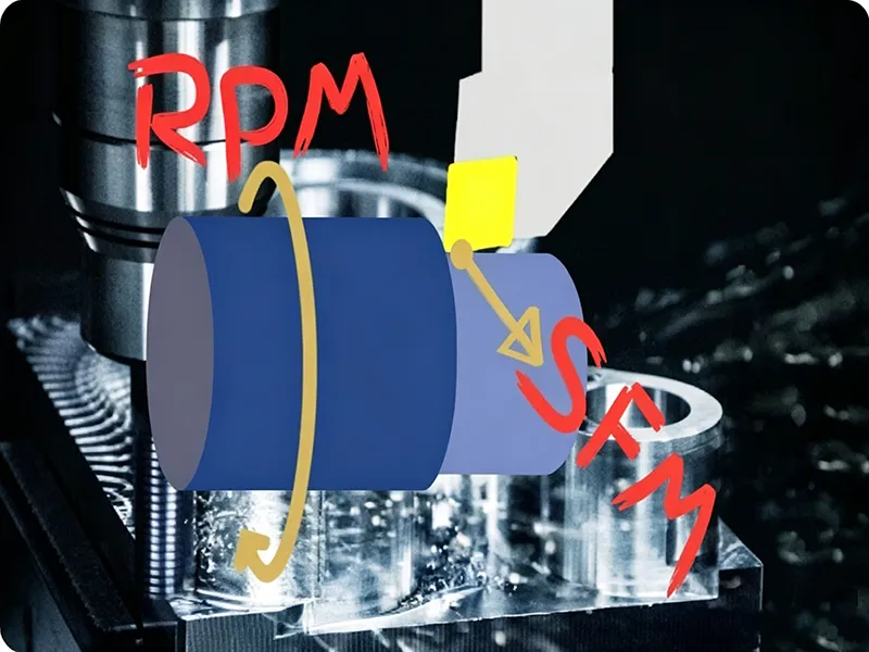
SFM (Surface Feet per Minute) is defined as the linear distance (in feet) that a point on the cutting tool’s edge travels in one minute. It’s effectively the cutting speed of the tool’s surface. In practical terms, SFM = π × (tool diameter in inches) × (spindle RPM) / 12. This combines tool/workpiece diameter and rotational speed into a single velocity. For example, a larger tool diameter at a given RPM will have a higher SFM (its edge moves faster through space) than a smaller tool at the same RPM. Machinists use SFM to determine how fast to spin the cutter when cutting different materials. Cutting speed (SFM) values vary by material: softer metals like aluminum can be cut at very high SFM, while hard materials like stainless steel or titanium require lower SFM. The term literally comes from the movement of the cutting surface: it’s how many feet per minute the surface moves relative to the workpiece.
SFM is essentially synonymous with cutting speed. In imperial units we say SFM; in metric units, this is often given as m/min. For example, 1000 ft/min ≈ 305 m/min. Because many machining handbooks and tool catalogs use imperial units, SFM remains common in the US and industries using US equipment.
Why SFM Matters in Machining
Choosing the correct SFM is crucial because it directly affects machining performance and results:
- Tool Life: If SFM is too high, the tool quickly overheats and dulls (or even fractures). If SFM is too low, the tool may rub instead of cutting, causing premature wear. In other words, incorrect SFM either overheats or over-stresses the cutter, shortening tool life. Using the proper SFM ensures tools last longer and reduces tooling costs. As WayKen notes, running at the right surface speed “ensures the tool lasts longer” and saves money on replacements.
- Surface Finish: SFM controls the smoothness of the machined surface. At the optimal SFM, each cut cleanly shears material, yielding a fine finish. If SFM is too fast or too slow, the cut quality degrades: surfaces may be rough, burnt, or wavy. For precision parts (like aerospace or medical components), achieving the correct SFM helps meet tight finish tolerances. As one CNC guide explains, “getting this speed right helps ensure quality…a fine surface is very important”. Poor surface finish often means extra polishing or scrapping parts, so correct SFM avoids rework.
- Machining Efficiency and Cycle Time: The right SFM maximizes material removal rate without damaging the tool. When SFM is optimized, the machine removes more material in less time, increasing throughput. In production, that means lower cost per part and higher profitability. Conversely, an SFM that is off-spec can slow down cutting or force extra passes. In short, correct SFM speeds up production and maintains tool health.
- Material Considerations: Different materials demand different SFM. Softer materials (like aluminum) can be cut at very high SFM, while harder or tougher materials (like steel or titanium) must use lower SFM. For instance, a typical 6061 aluminum alloy might run at 800–1500 SFM, whereas 303 stainless steel is often machined at only ~120 SFM. Using too high an SFM on hard materials will overload the tool and heat it, while too low an SFM on soft metals wastes time. Thus, matching SFM to material properties is key.
- Interaction with Machine Settings: SFM is linked to RPM and cutter size. If you change the tool diameter, you must change RPM to keep the same SFM. For example, doubling the tool diameter requires halving the RPM for the same SFM. Failing to adjust RPM when tool size changes will lead to incorrect cutting speeds. In summary, SFM is not an isolated setting but part of the overall speeds/feeds combination. A machinist must balance SFM with RPM (and feed) for the whole system to perform correctly.
How SFM Is Calculated
Basic SFM Formula
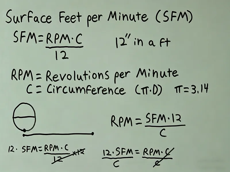
The formula for SFM (in imperial units) is:
[ \text{SFM} = \frac{\pi \times D \times \text{RPM}}{12} ]
where D is the cutter diameter in inches, and RPM is the spindle speed (revolutions per minute). This yields surface feet per minute. For example, if a 1-inch diameter cutter runs at 1,000 RPM, then SFM = (π×1×1000)/12 ≈ 262 ft/min (often rounded to 262.78). The constant 12 converts inches×rpm to feet/min (12 inches = 1 foot).
This formula can be rearranged or given in a “cookbook” form. Many machinists remember a simplified factor:
- SFM to RPM: RPM = (SFM × 12) / (π × D).
- RPM to SFM: SFM = (RPM × D) × 0.2618, since 0.2618 = π/12.
Harvey Tool’s guidelines present it as:
RPM = (3.82 × SFM) / D.
This comes from rearranging the SFM equation (3.82 ≈ 12/π). Thus, given any two of RPM, tool diameter, and SFM, you can compute the third.
Calculating RPM from SFM
Often you start with a recommended SFM and need to know what spindle speed (RPM) to run. Rearranging the formula:
[ \text{RPM} = \frac{\text{SFM} \times 12}{\pi \times D}. ]
For example, suppose the recommended SFM for machining 6061-T6 aluminum with a given cutter is 800 ft/min. If your tool is 0.5 inches in diameter, then:
[ \text{RPM} = \frac{800 \times 12}{\pi \times 0.5} \approx 6103\ \text{RPM}. ]
Using the quick factor, RPM ≈ (3.82 × 800)/0.5 ≈ 6100. Many CNC controls even accept SFM inputs and convert them using this formula.
SFM vs Cutting Speed in Metric Units
In metric systems, cutting speed is often given in meters per minute (m/min). To convert, multiply SFM by 0.3048 (since 1 foot = 0.3048 m). Likewise, to go from m/min to SFM, multiply by 3.281. The underlying physics is the same; it’s just a units change. For instance, 1000 SFM ≈ 305 m/min. Charts and software often display both units so machinists worldwide can use them.
SFM in Different Machining Processes
SFM in Milling
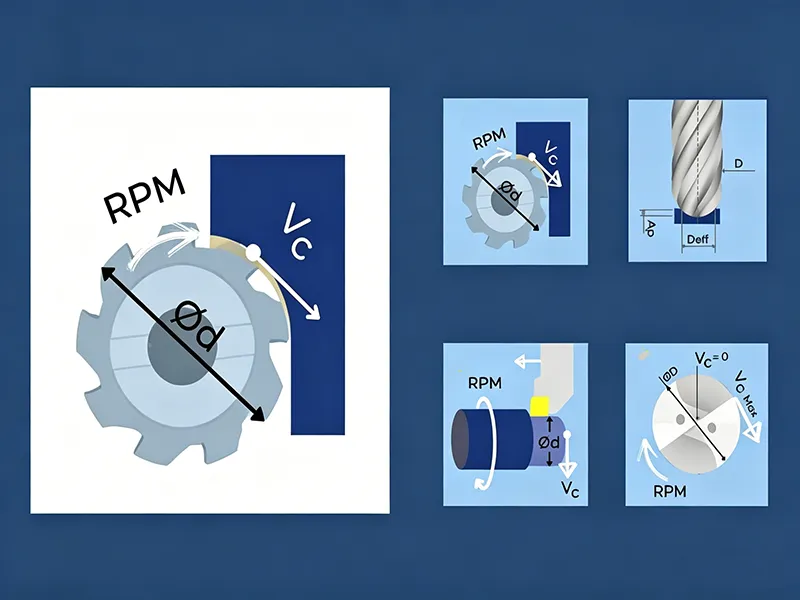
In milling operations, the SFM formula still applies using the cutter diameter. The milling machine’s spindle drives the cutter at a set RPM, and SFM is calculated from that RPM and the end mill’s diameter. Using the correct SFM in milling ensures efficient material removal. For example, DekMake explains that in milling “using the right SFM lets you remove material faster,” meaning parts complete more quickly without over-stressing the tool.
Conversely, if milling SFM is set improperly, problems arise. Excessive SFM will overheat the cutter; too little SFM will produce rough cuts. DekMake notes that in milling, if the speed is too high the tool overheats and if too low the finish suffers – “So, you need to set the right SFM to get a smooth finish.”.
Figure: Milling an aluminum part. In milling, the cutter’s surface speed (SFM) is set by spindle RPM and cutter diameter.
SFM in Turning
In turning (lathe) operations, the workpiece rotates against a stationary cutting tool. The same SFM formula applies, but D is now the workpiece diameter. The spindle speed of the lathe and the workpiece diameter determine the SFM at the tool edge. Again, correct SFM is key: too high and the tool overheats, too low and the surface is rough. As DekMake puts it for turning, “if your speed is too high during turning, the tool can get too hot and ruin the surface. If it’s too low, the surface comes out rough.”. In practice, turning charts give SFM values based on material and tooling, which are converted to RPM using the turning diameter.
SFM in Drilling (and Boring/Reaming)
Drilling, boring, and reaming holes also involve the same concept. The drill bit or reamer rotates, and the diameter of the bit determines the SFM at a given RPM. Using the right SFM prevents drill bits from dulling or breaking. For instance, DekMake notes in drilling “the right SFM keeps the drill bit from wearing out too fast” and ensures holes are accurate. If SFM is too high on a drill, the bit overheats; too low and it may chatter or wander. Likewise, boring and reaming (essentially refining a hole) rely on proper SFM to maintain hole quality.
Process Variations
While the SFM concept is the same, recommended SFM ranges differ by process and tool. Milling cutters often run at higher SFM than drills or reamers in the same material, partly due to tool material differences. In all cases, you first consult material-specific SFM tables (see next section) and then apply the formula to set RPM for the given diameter. Remember that coolant, tool geometry, and machine constraints can further influence the optimal SFM for each process.
Recommended SFM for Common Materials
Different materials have vastly different recommended surface speeds. The table below gives typical starting SFM ranges for various workpiece materials. These are general guidelines; actual values depend on tool material (HSS vs carbide), coatings, and cutting conditions.
| Material | Recommended SFM Range (ft/min) | Notes |
|---|---|---|
| Aluminum | 500–1500 | High values since aluminum is soft. (Cast alloys ~500–1000, wrought ~800–1500.) |
| Mild Steel | 100–300 | Low carbon and alloy steels. |
| Stainless Steel | 100–350 | Austenitic grades (304/316) ~60–140, but general practice 100–350. |
| Cast Iron | 50–150 | Gray and ductile cast iron (often run on the lower end to avoid thermal distortion). |
| Titanium | 100–200 | Very low SFM (e.g. Ti-6Al-4V at ~120–160) due to hardness and heat issues. |
| Plastics | 500–1500 | Plastics machine easily but can melt; moderate to high SFM is common. |
Source: Manufacturers’ recommendations and machining guides. Actual achievable SFM depends on cutter material and application, so use these as a starting point.
Factors That Affect SFM Selection
Several factors influence the choice of SFM beyond just the workpiece material:
- Workpiece Material: Hardness, strength, and thermal properties change the ideal SFM. Hard or tough materials (like stainless steels and superalloys) require lower SFM to avoid tool and work damage, while soft materials (aluminum, brass) can tolerate much higher SFM. For example, machining 6061 aluminum might use ~1000 ft/min, whereas 303 stainless steel with HSS tooling is only ~120 ft/min.
- Cutting Tool Material and Coating: Tool composition is critical. High-Speed Steel (HSS) tools are tough but can’t handle as high SFM as carbide. Carbide (and coated-carbide) tools run much faster. As DekMake notes, “HSS tools…you need to run them at lower SFM…Carbide tools can handle more heat…and you can use higher SFM”. Coatings like TiN or TiAlN further reduce friction, letting you increase SFM safely.
- Tool Diameter: Larger tools cover more surface distance per revolution. In practice, if you switch from a smaller to a larger diameter cutter, you must decrease RPM so that the SFM stays within the recommended range. In other words, a larger diameter tool at the same RPM will yield higher SFM, so you adjust RPM to compensate.
- Coolant/Lubrication: Using cutting fluids can often allow you to run higher SFM by dissipating heat and reducing friction. In dry cuts, you may need to reduce SFM to avoid overheating.
- Machine Rigidity and Power: A very rigid, high-powered machine can often run higher SFM without chatter. On a less rigid setup or smaller machine, you may have to reduce SFM to maintain stability.
- Depth of Cut and Feed Rate: While SFM is independent of feed, very heavy depths of cut might require slowing SFM to control forces and heat. Similarly, if you increase feed rate (chip load), you may need to slightly reduce SFM to keep the overall cutting load manageable.
In summary, the starting SFM should come from material and tool recommendations (e.g. machinist tables or calculators), but the actual SFM is tuned by these factors. As DekMake emphasizes, you can’t just set one parameter in isolation – tool material, diameter, and other settings must be considered together.
SFM vs Feed Rate: What’s the Difference?
It’s common to confuse cutting speed (SFM) with feed rate, but they describe different things, as shown in this cutting speed vs feed rate article. Cutting speed (SFM) refers to how fast the tool surface moves (rotational speed), while feed rate (often in inches/minute) is how fast the tool advances through the material (linear speed). As Datron explains: “cutting speed…is the velocity at which the cutting tool moves across the workpiece surface… Feed rate pertains to the linear motion of the tool along the workpiece”.
In other words, SFM is about the spindle/tool rotation and surface contact speed, whereas feed rate is about the tool’s advance per time. Both must be set appropriately: SFM dictates chip formation speed and heat generation, while feed rate influences chip thickness and material removal per revolution. A high SFM with too high a feed can overload the tool; a low feed with high SFM might just rub. They work together: you pick an SFM for your material, then choose a feed based on chipload (IPT) and depth of cut.
Note: A common mistake is to focus on SFM alone and forget feed (or vice versa). It’s important to balance both. A good rule is to consult tool manufacturer charts, which typically give recommended SFM and chip loads together.
Common Mistakes When Choosing SFM
Mistakes in SFM setup can ruin a job. Common pitfalls include:
- Setting SFM Too High: Leads to excessive heat and rapid tool wear. The cutting edge overheats and dulls, and the part can warp. High SFM also risks burning or melting softer materials.
- Setting SFM Too Low: Causes poor cutting action – the tool tends to rub instead of cut. This increases cutting forces, can generate chatter, and results in a rough finish. Low SFM also wastes time (slow material removal).
- Ignoring Tool Material: Using the same SFM for HSS and carbide tools is wrong. Always check if the tool can handle the chosen speed. As one guide warns, “Not accounting for tool wear…reduce the cutting performance and influence the SFM needed”. In practice, if a carbide insert recommends a higher speed, don’t substitute an HSS tool at the same SFM.
- Ignoring Workpiece Material: Using a “generic” SFM instead of one tailored to the material causes trouble. AT-Machining notes it’s a mistake to “use generic values that don’t account for the machined material since different materials require varying SFM”. Always ensure the SFM matches the specific material’s requirements (e.g. different steel grades or alloys have different optimal speeds).
- Not Considering the Whole System: Setting SFM without adjusting RPM/diameter or ignoring feed/depth of cut. Remember SFM is tied to RPM and diameter – you can’t arbitrarily pick SFM without converting it properly. Also, don’t focus on SFM alone; if you push SFM higher without adjusting feed, you may overload the tool.
By avoiding these errors and following manufacturer recommendations, you can select a safe and effective SFM. In particular, always double-check unit conversions and tool data to avoid calculation mistakes.
How to Optimize SFM for Better Machining Results
To dial in the best SFM for a job:
- Start with Recommendations: Consult tool and material handbooks or Machinist’s calculators. Use the tool maker’s recommended cutting speed as a baseline. Many find it easiest to enter the material and tool in software or charts to get a starting SFM.
- Adjust by Finish and Tool Wear: After initial cuts, inspect the surface finish and the tool. If the finish is too rough, try lowering or raising SFM slightly as appropriate. If the tool is discolored or worn quickly, back off the SFM. Often the “sweet spot” is found through a few trial cuts, observing chip color and finish quality.
- Optimize for Material Removal: If production rates are low, you can carefully increase SFM (or feed) while watching tool life. Conversely, if heat is an issue, reduce SFM. High-efficiency machining strategies may use higher SFM with special toolpaths, but only if the tool and machine can handle it.
- Keep Records: Once you find an SFM that works well for a given part/tool, note it. Experience and data-logging in CAM programs help refine the values over time.
In practice, optimizing SFM is iterative. Start with published values, then tweak up or down based on the actual machining conditions, keeping an eye on tool wear and part quality.
Practical Examples of SFM in Machining
- Milling Aluminum (6061-T6): Suppose a 0.50″ end mill is used. Recommended SFM for 6061-T6 might be around 1000 ft/min. Using the formula RPM = (3.82 × SFM)/D, we get RPM = (3.82 × 1000)/0.50 ≈ 7640 RPM. So you’d program the mill to ~7600 RPM for that cutter in 6061 aluminum.
- Turning Stainless Steel (304 SS): A 4″ diameter bar with recommended SFM ~100 ft/min (to use a round number). RPM = (100 × 12)/(π × 4) ≈ 95 RPM. In practice, you’d run the lathe around 90–100 RPM to hit ~100 SFM on a 4″ bar with that steel.
- Drilling Mild Steel: A 0.25″ drill bit in mild steel (S45C). If typical SFM is ~100 ft/min for HSS in mild steel, then RPM = (100 × 12)/(π × 0.25) ≈ 1528 RPM. So roughly 1500–1600 RPM for a 1/4″ drill in mild steel yields the right cutting speed.
These examples use the basic formula (or the 3.82 factor) to convert between SFM and RPM. Note that adjustments might be made if using carbide tooling or peck drilling, but the math illustrates the principle.
SFM Chart and Reference Tips
Experienced machinists often use SFM charts and calculators as quick references. These tools list recommended SFM values for materials and tool types. For example, a chart might say “6061 aluminum – 800 ft/min (HSS)” and “Cold-rolled steel – 60 ft/min (HSS)”. DekMake suggests using online SFM calculators or charts, which “list recommended SFM values for different materials” and make RPM conversion automatic.
However, take charts as a starting point. Real-world conditions (machine rigidity, fixture, coolant) may require deviation. Always verify with a test cut. When using charts:
- Double-check the material grade (e.g. 304 vs 316 stainless).
- Check if values assume HSS or carbide tooling.
- Be aware of unit conversions (SFM vs m/min).
In summary, SFM charts and machinist calculators are convenient, but always tailor the values to your specific setup and observe the results.
Summary
Surface Feet per Minute (SFM) is the measure of cutting speed in machining. It’s calculated from cutter diameter and spindle RPM, and is the standard way to specify how fast a tool moves through the material. The correct SFM is critical: it affects tool life, surface finish, and cycle time. We’ve covered how to compute SFM (and its converse, RPM) and why it must be matched to material and tooling. Common materials (aluminum, steels, titanium, plastics, etc.) each have typical SFM ranges. Factors like tool material, diameter, coolant, and machine rigidity also influence the optimal SFM. Using charts or calculators can guide selection, but always verify with test cuts and adjust as needed using a reliable speeds and feeds reference. In practice, setting the right SFM (along with proper feed rates and depths) is essential for efficient, high-quality machining.
FAQ
What does SFM mean in machining?
SFM means Surface Feet per Minute. It is the speed (in feet/minute) of the cutting tool’s surface relative to the workpiece. It quantifies the cutting speed of a tool.
How do you calculate SFM?
Use the formula: SFM = (π × D × RPM) / 12, where D is tool or part diameter in inches and RPM is spindle speed. For example, SFM = (3.1416 × 1″ × 1000 RPM)/12 ≈ 262 ft/min.
What is the difference between SFM and RPM?
SFM measures the linear surface speed of the tool’s edge (in ft/min), whereas RPM is the rotational speed of the spindle (revolutions per minute). SFM depends on RPM and tool diameter. SFM tells us how fast material is being sheared; RPM is just how fast the tool spins.
Why is SFM important in machining?
Proper SFM ensures efficient cutting, long tool life, and good finishes. If SFM is wrong, tools can overheat or wear out, and the workpiece can burn or finish poorly. It directly impacts productivity and quality.
Does SFM change for different materials?
Yes. Harder or tougher materials require lower SFM; softer materials allow higher SFM. For example, aluminum runs at hundreds or thousands of SFM, while stainless steel often runs at just dozens to a few hundred. Each material has a recommended SFM range.
What happens if SFM is too high or too low?
If SFM is too high, the tool overheats and dulls quickly, and excessive heat can warp the part. If SFM is too low, the tool tends to rub and cut inefficiently, causing poor surface finish and slow material removal. Both situations shorten tool life and degrade part quality.

