

Shafts are cylindrical mechanical components that transmit torque and support rotating loads in machines. They connect power sources (motors, engines) to driven parts (gears, pulleys, bearings) and must withstand torsion, bending, and axial forces. Shafts appear in many systems — from electric motors, pumps, and gearboxes to automotive drivetrains and aerospace assemblies. This guide covers common shaft types, materials, manufacturing methods, design considerations, and applications.
What is a Shaft?
Engineering Library’s transmission shafting analysis also defines a shaft as a rotating member, usually circular, used to transmit power. Typically cylindrical (or stepped) in shape, a shaft carries rotating parts such as gears, pulleys, and couplings on its length. By rotating, it connects an energy source (like a motor) to driven equipment, carrying power from one end to the other. The shaft’s diameter, material, and surface finish determine its strength and precision – small errors (runout or misalignment) can cause vibration or premature wear in the machine.
How Do Shafts Work?
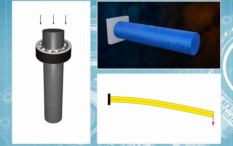
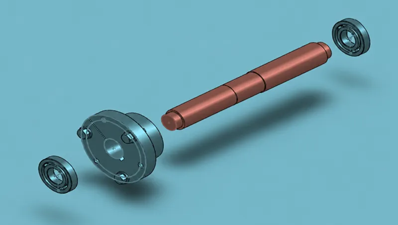
Shafts transfer power by connecting the driving component (motor, engine) to driven components (gear, pulley, wheel). When the power source turns the shaft, the shaft’s surface forcefully engages attached parts, causing them to rotate. In effect, shafts transmit power and torque through the machine. They also support and locate rotating parts: gears, bearings, pulleys and couplings mount on the shaft’s shoulders or journals. In doing so, the shaft endures shear, bending, and axial loads in addition to pure torsion. For example, a motor’s shaft might drive a pump impeller (power transmission), while bearings at either end keep the shaft aligned. Bearings reduce friction as the shaft spins. In summary: a shaft works as a rotating member that carries torque between components and provides mounting surfaces for rotating parts.
Main Types of Shafts
Shafts come in many forms depending on their function and geometry. Common shaft types include:
| Shaft Type | Main Function | Common Use |
|---|---|---|
| Transmission Shaft | Transfers power between machine elements | Gearboxes, power machinery |
| Drive Shaft | Delivers torque from one system to another | Vehicles (propeller shafts), motors |
| Axle Shaft | Supports wheels or rotating parts; sometimes transmits torque | Automotive axles, carts |
| Spindle Shaft | Holds and rotates tooling or workpieces at high speed | CNC machines, lathes, mills |
| Motor Shaft | Transfers torque from a motor’s rotor | Electric motors, generators |
| Gear Shaft | Supports or houses gears | Gearboxes, speed reducers |
| Step Shaft | Varying diameters for mounting bearings/gears | Bearing and gear assemblies |
| Hollow Shaft | Reduces weight or allows routing through its core | Aerospace, robotics, valve stems |
| Splined Shaft | Transmits torque via multiple grooves (splines) | Transmissions, couplings, drive systems |
| Precision Shaft | High tolerance and fine finish for accuracy | Instrumentation, precision automation |
Each type is engineered for its role. For example, transmission shafts (like line shafts or propeller shafts) carry large torque across distances, while spindle shafts are precision shafts in machine tools that require very tight runout and surface finish.
Transmission Shafts
Transmission shafts transfer power between different parts of a machine or system. These shafts carry engine or motor output to driven equipment. In many machines and gearboxes, a line shaft or countershaft relays torque from a power source to multiple components. For example, in automotive use the driveshaft (a type of transmission shaft) carries torque from the engine through the gearbox to the wheels. Transmission shafts must bear high torsion and bending loads. They are used in gear reducers, conveyors, pumps, and industrial machinery where torque is passed along from one element to another.
Drive Shafts
Drive shafts are often long, rotating shafts that deliver torque from one system to another. In vehicles (cars, trucks, propeller-driven vehicles), a drive shaft connects the engine output (via the gearbox) to the axle or propeller. For example, an automotive drive shaft transmits power from the engine to the wheels. Drive shafts must be well-balanced and strong in torsion. Long drive shafts often include splines, keyways, or flanges at their ends for reliable connections. Designers control their diameter and support spacing to minimize bending and vibration at high speeds. Proper design of drive shafts is critical in vehicles and rotating machinery to avoid whip and fatigue.
Spindle Shafts
Spindle shafts are precision shafts used in high-speed machinery. Common in CNC mills, lathes, and rotary tables, a spindle is a shaft that holds and rotates cutting tools or workpieces. Spindle shafts are manufactured to very tight tolerances and balanced to high precision because even a small misalignment can cause vibration at high RPM. They must have very smooth surfaces and often receive grinding and balancing. Spindles are designed for rigidity and accuracy; they can rotate at thousands of RPM while carrying loads. In short, spindle shafts enable accurate, high-speed rotation in machine tools and are critical to achieving tight machining accuracy.
Step Shafts
A step shaft (or stepped shaft) features multiple diameters (steps) along its length. Each larger-diameter shoulder provides a mounting location (or “step”) for bearings, gears, or pulleys. Between steps are smaller-diameter sections where components can slide on. Stepped shafts are easily made by CNC turning: after facing the ends, the lathe cuts each concentric diameter in sequence. Fillet radii are usually added at diameter transitions to reduce stress concentration. Step shafts are used wherever parts must be located at precise positions along the shaft — for example, a shaft carrying two gears and a bearing would use steps to seat each element accurately.
Splined Shafts and Keyed Shafts
Splined and keyed shafts are used to lock rotating parts to a shaft. A splined shaft has multiple longitudinal grooves (splines) cut along its length. The mating part (gear or hub) has matching grooves; this allows torque transmission through many contact surfaces. Keyed shafts have a single keyway slot and use a removable key to prevent relative rotation with a mounted part. Both methods prevent slipping: splines carry higher loads and are self-centering, while keys are simpler. These features are widely used in transmissions and couplings. For example, a splined shaft might drive a gearbox gear, whereas a keyed hub on a shaft might hold a pulley. Machining keyed or splined shafts typically involves milling or broaching, followed by grinding to finish the profiles.
Hollow Shafts
A hollow shaft is simply a shaft with its center bored out. By removing the core, a hollow shaft weighs less and has less rotational inertia while still transmitting torque. Designers use hollow shafts when weight or material saving is important. The hollow center can also route cables, fluids, or allow a tight fit over another member. Hollow shafts are common in robotics (to run wires through joints), aerospace (for lightweight rotors), and precision equipment. The wall thickness is chosen to balance strength and stiffness; too thin and the shaft may buckle, too thick and it negates weight savings. In summary, hollow shafts provide a lightweight alternative to solid shafts when torsional requirements allow.
Common Shaft Materials
Shafts must be made from materials that meet strength, wear, and environmental needs. Common materials include:
- Carbon Steel Shafts: Medium-carbon steels (e.g. 1045, 4140) are most common due to their high strength, toughness and low cost. They machine well and can be heat-treated for extra hardness. Carbon steel shafts are used in general machinery, conveyors, and low-cost applications.
- Stainless Steel Shafts: Used where corrosion resistance is needed. Stainless alloys (303, 304, 316) resist rust and chemicals, making them ideal for food, marine, medical, or outdoor environments. Stainless shafts are common in pumps, valves, and medical devices. (They machine slower and often work-harden.)
- Alloy Steel Shafts: Alloy steels (e.g. 4340, 4140) contain elements like Ni, Cr, Mo for higher strength, toughness and wear resistance. These can be heat-treated to very high hardness. Alloy shaft materials are used in heavy-duty or high-torque applications (driveshafts, gears, heavy machinery) where fatigue resistance is critical.
- Aluminum Shafts: Aluminum alloys are lightweight and corrosion-resistant. They suit weight-sensitive applications (aerospace, automotive, drones) where loads are moderate. Aluminum shafts (6xxx series, etc.) are easier to machine but have lower hardness. They are used when saving weight outweighs strength needs.
- Brass/Copper Shafts: Brass and bronze alloys offer good corrosion resistance, lubricity, and machinability. They are often used in electrical or low-speed mechanical systems (like plumbing valves, low-speed gears) where anti-galling and anti-microbial properties are helpful.
- Titanium Shafts: Titanium alloys have an excellent strength-to-weight ratio and corrosion resistance. They appear in aerospace, military, and medical shafts where premium performance is required despite high cost. Titanium shafts handle high stress and harsh environments, but are expensive and hard to machine.
Each material trades off properties. Carbon/alloy steels are “workhorses” for most shafts, while stainless, aluminum or titanium are chosen for special requirements like corrosion, weight, or high performance.
How Are Shafts Manufactured?
Shaft production usually involves shaping a metal blank followed by precision machining and finishing. A typical process is:
- Stock Preparation: Shafts often start as forged, rolled or extruded bars for good grain structure.
- CNC Turning: A CNC lathe roughs and finishes the round profile.
- It cuts the main diameter, steps, shoulders, tapers, threads, grooves, and performs the final facing.
- CNC Milling: Milling machines cut keyways, flats, holes or special contours into the already-turned shaft.
- Grinding: Cylindrical grinding is used on high-precision shafts to achieve tight roundness and surface finish. Grinding is common for spindle surfaces or bearing journals after turning.
- Heat Treatment: Shafts requiring high strength are heat-treated (e.g. quench & temper, case hardening, nitriding) to improve hardness and fatigue life.
- Surface Finishing: Additional processes like polishing, plating or coating (black oxide, zinc, nickel, anodize) improve corrosion resistance or appearance. Polishing or peening may also enhance surface strength.
CNC Turning
CNC lathes are the workhorse for shaft machining. Turning operations cut all round features: outer diameters, chamfers, shoulders, and create stepped profiles. Rough turning removes bulk material; finish turning brings dimensions to tolerance. Features like tapers and threads are cut on the lathe. CNC lathes achieve high precision and repeatability, making them ideal for any cylindrical shaft — from simple round bars to complex multi-step shafts.
CNC Milling
After turning, CNC milling adds non-round features. Keyways, flats, slots, cross-drill holes and grooves are milled into the turned shaft. For example, a milling cutter can slot a groove for a key or cut splines. Milling is also used to machine special profiles on the end of a shaft or to drill lubrication holes. In practice, shafts often undergo both turning and milling in a machining center to get all required geometries.
Grinding
Grinding is used for shafts requiring very tight tolerances or superior surface finish. A cylindrical grinder or centerless grinder will remove tiny amounts of material to smooth and correct the turned surfaces. Grinding is common on spindles, motor shafts, and bearing journals where roundness errors must be minimized. It can also correct distortions from heat treatment. The result is a very smooth, precise surface.
Heat Treatment
Heat treatments enhance a shaft’s mechanical properties. Processes like quenching, tempering, induction hardening or nitriding increase hardness, strength and fatigue resistance. For example, drive shafts and crankshafts are often hardened and tempered so they can handle high torque and impact loads. After heat treatment, shafts may be ground again for final dimensions.
Surface Finishing
Common finishes include polishing, black oxide, zinc plating, nickel plating, and anodizing (for aluminum). These improve corrosion resistance, reduce wear, and sometimes enhance appearance. For instance, nickel plating on a steel shaft can prevent rust in wet environments, while polishing a spindle shaft improves its runout and longevity. Surface coatings and precision polish can significantly extend shaft life in harsh conditions.

Key Design Considerations for Shafts
Designing a shaft requires balancing strength, stiffness, and manufacturability. Key considerations include: shaft diameter and length (must carry the required torque without excessive deflection); the load type (torsion, bending or axial load) and resulting stress calculations; bearing fits (clearance or interference) where bearings mount; and features like keyways, splines or threads that will be cut. Designers must also specify surface roughness and tolerance requirements to match mating parts. Other factors are material hardness (often needing heat treatment), environmental factors (corrosion, temperature), and dynamic behavior (balance to avoid vibration). In short, a good shaft design must ensure that it meets torque and load demands while maintaining precise alignment and reliable rotation.
Shaft Tolerances and Surface Finish
Tolerance and finish directly affect shaft performance. Tolerances determine how well the shaft fits into bearings, gears and couplings. Too loose a tolerance can cause misalignment and vibration; too tight can make assembly difficult or cause stress. Critical dimensions like journal diameters often require precision fits for bearings, and SKF provides useful guidance on bearing tolerances and resultant fits (e.g. H7/g6). Runout (deviation from true axis) must be minimized, especially for high-speed shafts, to avoid imbalance.
Surface finish also matters: a smooth shaft surface reduces friction and wear. For example, a finely ground or polished journal allows longer bearing life and quieter operation. In motor shafts and spindles, very low roughness and tight roundness are required. Both tolerances and finish must be controlled through machining and grinding to meet the shaft’s design specifications.
Common Shaft Applications
Shafts are everywhere in engineering. In automotive systems, they appear as driveshafts, axles, crankshafts and camshafts for powertrain components. In industrial machinery and automation, shafts transmit power in pumps, compressors, mixers, conveyors and gearboxes. They also turn wheels on robots and actuators. In aerospace, shafts are used in engines (turbine shafts) and landing gear mechanisms, often requiring lightweight materials. In medical and electronics, small precision shafts might be found in instrumentation, pumps or motors. Overall, any system involving torque transmission, rotation or precise motion may rely on one or more shafts.
For example, automotive drive shafts (shown) connect a car’s engine to its wheels, while industrial shafts (not pictured) power heavy machinery.
Custom Shafts in CNC Machining
Standard off-the-shelf shafts don’t cover every need, so custom shafts are often CNC-machined to print. CNC turning and milling allow making shafts of special dimensions, multiple steps, keyed features, threads, and precise tolerances. A custom shaft can be machined in small or large quantities. Our CNC services can produce custom steel, aluminum, or exotic alloy shafts with any diameter, length or feature (steps, splines, flats, holes) as specified. This flexibility supports industries like automotive, aerospace, medical or robotics that have unique shaft requirements.
Common Shaft Problems and How to Avoid Them
- Bending or deflection: Slender shafts may flex under load, causing runout. Avoid by increasing diameter, adding supports (centers or steady rests) during machining, or using stiffer material.
- Excessive runout: Poor concentricity leads to vibration. Machine carefully (or grind) and inspect on a CMM. Ensure proper clamping and tool setup.
- Poor bearing fit: If journals are too loose or tight, bearings can slip or pinch. Use correct tolerance class and finish for bearing seats.
- Surface wear or corrosion: In hostile environments, shafts can rust or gall. Use appropriate material (stainless steel or coatings) and lubrication to prevent seizing.
- Fatigue failure: Repeated loads can cause cracks. Minimize stress concentrations (add fillets), use high-fatigue-strength materials, and consider surface treatments (shot peening) to improve fatigue life.
- Thread or keyway cracking: Sharp corners can be crack starters. Chamfer threads, radiused keyways, and avoid over-tightening fasteners.
- Dimensional drift: During long machining cycles, heat buildup can expand the shaft. Control cutting parameters and allow cooling stages for precision parts.
By accounting for these issues in design and production (proper materials, adequate heat treatment, precise machining, and inspection), many shaft failures can be prevented.
How to Choose the Right Shaft
When selecting or designing a shaft, start by defining the operational requirements. Consider the torque, loads (axial/bending), speed, and power it must carry. Determine the length and diameter needed for strength and stiffness. Choose a material that meets strength and environmental needs (e.g. steel for general use, stainless for corrosion, aluminum for light weight). Specify critical features: keyways, splines, threads, shoulders. Define bearing fits, surface finish and tolerance classes based on mating components. For high-speed shafts, dynamic balance is crucial. Finally, consider manufacturing: a well-chosen material and simple geometry can reduce cost and lead time. In summary, match the shaft’s design (size, material, features, tolerances) to the application’s torque, speed, and environment requirements for the best performance and value.
Conclusion
Shafts are fundamental components used to transmit rotation, torque and motion in mechanical systems. They range from simple cylindrical bars to complex stepped, splined or hollow shafts, each suited to specific tasks. Different shaft types — such as transmission shafts, drive shafts, spindle shafts and step shafts — serve different roles in power transmission and support. Material choice (carbon/alloy steel, stainless, aluminum, etc.) and manufacturing (CNC turning, grinding, heat treatment) determine a shaft’s strength and durability. Proper design and machining ensure shafts meet tight tolerances and surface finish for reliability. In automotive, aerospace, industrial machinery and many other fields, well-designed shafts are critical for efficient, long-lived power transmission. With the right shaft type, material and precision manufacturing, engineers ensure optimal performance in any rotating machinery.
FAQ About Shafts
What are shafts used for?
Shafts are used to transmit rotary motion and torque between components. They carry power from motors or engines to gears, pulleys, or wheels, while also supporting those rotating parts. For example, a motor’s shaft drives a pump impeller, or a car’s driveshaft transmits engine torque to the wheels.
What are the main types of shafts?
Common shaft types include transmission shafts (for power transfer across machine elements), drive (propeller) shafts (in vehicles and drives), axle shafts (support wheels), spindle shafts (in machine tools), step shafts (with varying diameters), splined/keyed shafts, hollow shafts, and precision shafts. Each type is designed for its specific role and load conditions.
What materials are used for shafts?
Typical shaft materials are carbon and alloy steels (strong and easy to machine), stainless steel (for corrosion resistance), aluminum (lightweight), brass (low friction), and titanium (high strength-to-weight). The choice depends on strength, corrosion resistance, and weight requirements.
How are shafts manufactured?
Shafts are usually turned on CNC lathes to form their main shapes. After turning, CNC mills cut keyways, flats, or holes. High-precision shafts are then ground for tight tolerances. Heat treatment and surface finishing (polishing, plating) are applied as needed. Forging or extrusion may precede machining to create the initial bar stock.
What is the difference between a shaft and an axle?
A shaft is primarily for transmitting torque and motion between machine parts. An axle (often found in vehicles) mainly supports weight and can rotate but isn’t always intended to transmit significant power. Axle shafts bear the vehicle’s load, whereas drive shafts transmit engine torque.
Can shafts be custom machined?
Yes. Custom shafts can be CNC machined to any specified diameter, length, and feature (steps, splines, threads, keyways, etc.). CNC turning and milling allow low-volume or one-off production of special-dimension shafts. This flexibility makes it possible to produce precision shafts for prototype, replacement, or specialized applications as needed.

