
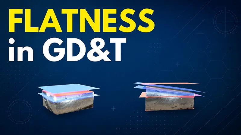
Flatness is a GD&T form tolerance used to control how much a single surface may depart from a perfect plane, and unlike datum-related controls, it does not need a datum reference. In ASME Y14.5 Dimensioning and Tolerancing aligned descriptions, flatness creates a tolerance zone between two parallel planes within which the surface must lie; because that zone “floats,” flatness by itself does not control location or orientation. That makes it especially useful for sealing faces, mounting pads, machined plates, brackets, housings, and other functional surfaces where contact, stability, heat transfer, or leakage risk matter. In practical manufacturing, flatness has a direct effect on assembly fit, sealing quality, thermal contact, and part performance. This guide explains what flatness in GD&T means, how flatness tolerance works, how flatness is measured, and what machining and inspection choices help control flatness without adding unnecessary cost.
What Is Flatness in GD&T?
Flatness in GD&T is a GD&T form tolerance. It limits how far a real surface may deviate from an ideal plane, but it does not locate that surface, orient it to another feature, or establish its position in space. In other words, flatness answers a single question: How flat is this one surface by itself? Official GD&T references describe form tolerances as independent of datums, and flatness specifically as a surface that must remain between two parallel planes separated by the stated tolerance value.
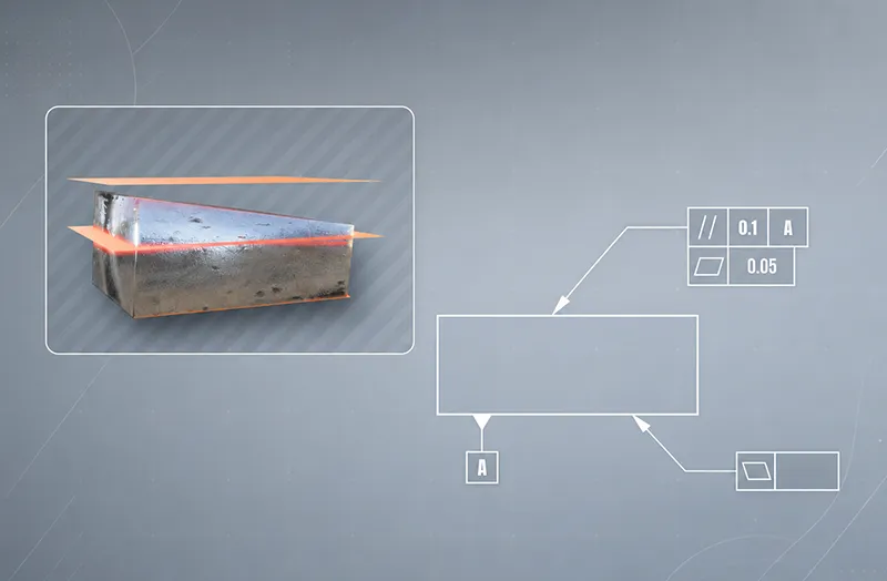
This is why flatness is different from many other GD&T controls. It is applied to an individual surface, not to a relationship between two features. If a designer wants to control the surface’s angle relative to another reference, flatness alone is not enough; that is the job of a datum-related orientation control such as parallelism.
Under ASME practice, flatness of a surface and flatness of a derived median plane are treated separately. Most shop-floor discussions of “flatness” refer to the surface case, which is the focus of this guide. ISO GPS practice also treats flatness as a core geometrical tolerance, with ISO 1101 geometrical tolerancing covering geometrical tolerancing fundamentals and ISO 12781 defining flatness-related vocabulary and specification concepts for integral features.
Why Flatness Matters in Manufacturing
Flatness matters whenever one surface must mate, seal, support, transfer heat, or sit stably against another. Creaform notes that flatness is particularly useful when two surfaces must come together to form a tight seal. TDK-Lambda’s heatsink guidance likewise requires a flat mating surface and warns that flatness irregularities create gaps that increase thermal contact resistance. Onsemi shows a similar effect in power packages: warpage and mounting-surface flatness can worsen contact with the heat sink and affect thermal performance.
That is why flatness shows up so often on mounting plates, flanges, housing faces, machine feet, brackets, sealing lands, and heat-transfer interfaces. In machine installation, Easy-Laser notes that equipment manufacturers assume machines are installed on flat and level surfaces, and it cites installation flatness and coplanarity recommendations from ANSI and ISO contexts. Polytec also notes that flatness is functionally important for sealing surfaces, valve seats, precision mechanics, PCBs, and moving surfaces where noise and reliability can be affected.
In simple practical terms, poor flatness can lead to rocking on a mounting face, uneven bolt loading, localized contact instead of full contact, leakage on sealing surfaces, or poor thermal coupling across a contact pad. For precision CNC parts, those are not abstract drafting problems; they are real functional failures that show up during assembly, testing, or service.
How Flatness Tolerance Works
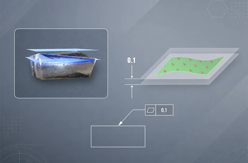
A flatness tolerance creates a zone between two parallel planes. Every point on the controlled surface has to fall inside that zone. FARO’s ASME-based explanation describes flatness as a tolerance zone defined by two parallel planes within which the surface must lie, while Keyence explains the same concept as the distance between the most protruding and most concave parts of the surface.
The important detail is that the zone is not locked to a datum. FARO emphasizes that the two planes are not necessarily aligned with anything else, which is why flatness controls shape only, not orientation. So if a drawing specifies flatness of 0.05 mm, the surface passes only if all measured points can be enclosed within a pair of parallel planes 0.05 mm apart, regardless of how those planes are tilted in space. A smaller number means a tighter requirement and less permitted variation.
In ISO metrology, the underlying idea is the same, but the evaluation details can vary with the standard and data treatment. Polytec notes that ISO 1101 defines flatness through the smallest possible distance between two parallel planes containing all measured points, while ISO 12781 provides a broader framework that depends on prior form-removal choices. That distinction matters when tolerances get tight, because different evaluation strategies can produce different numerical results.

Flatness vs Straightness vs Parallelism
These controls are often confused because they all involve “how straight” or “how planar” a feature looks. The key difference is what is being controlled and whether a datum is required. Keyence’s GD&T guidance draws a clean line between form tolerances, which do not require datums, and orientation tolerances, which do. FARO also stresses that flatness is a floating two-plane zone rather than a datum-related relationship.
| GD&T control | What it controls | Requires datum? | Typical use |
|---|---|---|---|
| Flatness | An entire surface’s form | No | Sealing faces, mounting pads, machined plates |
| Straightness | A line element or an axis | No | Long edges, shafts, individual line elements |
| Parallelism | Orientation of a line or plane relative to a reference | Yes | Surfaces or axes that must stay aligned to a datum |
Straightness in Keyence’s definitions is applied to lines rather than planes, while parallelism explicitly references a datum and controls orientation. That means a surface can be very flat but still not be parallel to another feature, and it can be parallel to a datum while still needing separate control of local form if the design intent is especially demanding.
How Flatness Is Measured in Practice
ASME-based metrology guidance makes an important point: the standard defines the tolerance zone, but it does not prescribe one universal gaging method for every situation. Mitutoyo’s ASME Y14.5 training notes that the standard defines tolerance zones only, and that measurement planning must consider cost, purpose, and the consequences of pass/fail decisions. That is why flatness can be checked in different ways depending on part size, tolerance, surface accessibility, and whether the job is shop-floor inspection or formal reporting.
Common methods are summarized below. The table combines official guidance from Keyence, Mitutoyo, Starrett, ZEISS, Polytec, and PTB.
| Method | Best fit | Main advantage | Main limitation |
|---|---|---|---|
| Surface plate with surface gage, height gage, or indicator | Routine inspection of machined parts | Simple, familiar, cost-effective | Result depends heavily on point coverage and setup discipline |
| Dial indicator sweep | Workshop-level checking and troubleshooting | Quickly reveals high and low areas | Manual reads can vary with operator and point path |
| CMM | Precision CNC parts and documented inspection | Multi-point measurement, repeatable reporting, high precision | Point-by-point measurement can miss local deviations if sampling is sparse |
| Optical or laser measurement | Thin, delicate, soft, or very high-precision surfaces | Non-contact, dense point clouds, full-field mapping | Equipment cost and data-processing choices matter |
Keyence shows a classic dial-gauge method in which the part is placed on a precision plane and the surface is swept to find the largest deviation value. The same source notes that CMM flatness inspection becomes more stable as the number of measurement points increases. ZEISS describes CMMs as ideal for precise workpiece measurement and optical systems as appropriate where non-contact measurement is required. Polytec adds that optical full-field methods can capture millions of points quickly, while sparse point spacing on tactile systems may miss local surface deviations.
A practical flatness inspection process usually follows the same sequence: clean the part and fixture, stabilize the setup, choose a suitable instrument, measure enough points over the surface, calculate the flatness result, compare it to the drawing, and document the outcome. Creaform describes the core math as acquiring surface points, finding the smallest possible enclosure by two parallel planes, and using the distance between those limiting planes as the flatness result. Mitutoyo similarly describes practical assessment as measuring points across the surface and evaluating the range from the highest peak to the lowest value.
In real manufacturing, point strategy matters a lot. A NIST study on CMM flat-surface inspection plans found that sampling plan and sample size strongly affect how representative the measured range is. The study also warned that the common practice of inspecting only a handful of points can routinely underestimate the true range by more than 20% in many cases. That is one of the most important practical lessons in flatness inspection: a method is only as good as its data coverage.
One more nuance matters for tight-tolerance work. Polytec notes that ISO 1101 and ISO 12781 can differ in how the bounding planes are calculated, and Mitutoyo’s ASME presentation reminds users that measurement methods do not automatically “come from” the standard itself. For critical surfaces, it is wise to define the inspection method, sampling density, fitting algorithm, filtering rules, and acceptance criteria before production begins. Mitutoyo also highlights an ASME Y14.5-2018 rule change stating that, unless otherwise stated, surface elements include texture and flaws such as burrs and scratches, which can influence pass/fail results on very tight flatness callouts.

What Affects Flatness and How to Improve It
Flatness problems in machined parts usually come from a combination of material stress, workholding, cutting forces, heat, geometry, and the choice of CNC machining materials. NASA’s work on machining distortion shows that residual stress and heat treatment history can strongly affect warpage after material removal. The same study physically measured distortion after face cuts and found that stress-relief conditions could significantly reduce subsequent machining distortion. Georgia Tech’s fixture research adds that elastic deformation under machining and fixturing forces creates geometric errors, which is why clamp location and clamp force matter so much.
The causes and countermeasures below are the ones that most often matter in CNC machining. They are a synthesis of NASA, Georgia Tech, NIMS grinding guidance, and component flatness case studies from onsemi.
| Common cause | Why it hurts flatness | Practical response |
|---|---|---|
| Residual stress in stock | Material moves as metal is removed | Use stable stock, stress-relieved material, or intermediate stress-relief strategy |
| Excessive clamping force | Part bends during machining and springs back after release | Reduce clamp load, improve contact support, redesign fixture points |
| Thin walls or wide unsupported faces | Low stiffness amplifies deformation | Add support, stage machining, or revise geometry during DFM |
| Heat from cutting or post-processing | Thermal expansion and stress redistribution distort the part | Control process heat, coolant strategy, and finishing sequence |
| Inadequate finishing strategy | Roughing leaves uneven stock or stress imbalance | Balance roughing and finishing, leave consistent stock for final passes |
| Process capability too low for the tolerance | Milling alone may not hold the target | Add a finer finishing step such as precision grinding when function requires it |
For tight flatness requirements, process planning matters as much as machine accuracy. That usually means avoiding over-clamping, roughing symmetrically where possible, leaving enough stock for a controlled finish pass, and adding a higher-precision finishing operation when needed. NIMS surface-grinding guidance shows how ground flat surfaces are used to reach precision geometry and even lists flatness inspection as part of the acceptance criteria for a finished part.
Flatness Examples, Cost, and Final Guidance
The biggest costing mistake is treating flatness as “free.” It is not. As a practical inference from ASME-oriented measurement planning, NIST sampling research, NASA distortion studies, and precision finishing practice, tighter flatness usually raises cost because it narrows the allowed zone, increases the need for process control, may require finer finishing or fixture refinement, and often demands more inspection effort and denser data collection. Large flat surfaces and thin parts are especially difficult because they are more sensitive to distortion and harder to sample reliably.
The examples below are illustrative only, not universal standard defaults. They show how flatness is often specified according to function rather than habit.
| Part type | Example flatness callout | Why it may be used |
|---|---|---|
| General mounting plate | 0.10 mm | Helps the part sit stably in assembly without over-specifying cost |
| Sealing face on a housing or flange | 0.03 mm | Supports better contact and lower leakage risk |
| General welded or bolted bracket | 0.20 mm | Often sufficient when minor variation can be absorbed in assembly |
| Heat-transfer contact face | Function-driven, often tighter than general structure | Reduces gaps and improves contact consistency |
The right flatness tolerance is the one that protects function without forcing unnecessary process cost. If a surface only supports a loose bracket, a very tight callout may add inspection time with no real benefit. If the surface seals fluid, supports electronics cooling, or serves as a precision mounting reference, flatness often deserves much closer attention. Review it early in DFM review, choose an inspection method before production, and make sure the callout reflects the real job the surface has to do. In precision CNC machining, good flatness control is not just about making a part look planar on paper; it is about making the part assemble, seal, transfer load, and perform the way the design intended.
FAQs About Flatness in GD&T
What does flatness mean in GD&T?
Flatness is a GD&T form tolerance that limits how much one surface may deviate from a perfect plane. The controlled surface must fit within two parallel planes separated by the specified tolerance value.
Does flatness require a datum?
No. Flatness is a form control, and official GD&T guidance classifies form tolerances as independent of datums. A datum is needed for orientation controls such as parallelism, but not for flatness of a surface.
How is flatness measured?
Flatness can be measured with a surface plate and indicator-based setup, a dial indicator sweep, a CMM, or a non-contact optical or laser system. The best choice depends on part geometry, tolerance level, and whether the inspection is routine shop-floor checking or high-precision documented metrology.
What is the difference between flatness and parallelism?
Flatness controls the form of a single surface by itself. Parallelism controls the orientation of a surface or axis relative to a datum. A surface can be flat but not parallel to another feature, and parallelism cannot be specified without a datum reference.
Why does a tight flatness tolerance increase machining cost?
Because tighter flatness usually demands more stable fixturing, better process control, more careful stress management, denser inspection data, and sometimes a finer finishing process. NIST’s inspection research and ASME-oriented metrology guidance both show that measurement planning and sample coverage significantly affect confidence in flatness results.
How can flatness be improved in CNC machined parts?
The most effective methods are using stable material, reducing distortion from clamping, balancing roughing and finishing, allowing enough stock for the final pass, applying stress-relief strategies where needed, and adding a precision finishing step such as grinding when the function justifies it. These countermeasures directly address the residual-stress and fixture-force mechanisms that drive warpage and geometric error.

