
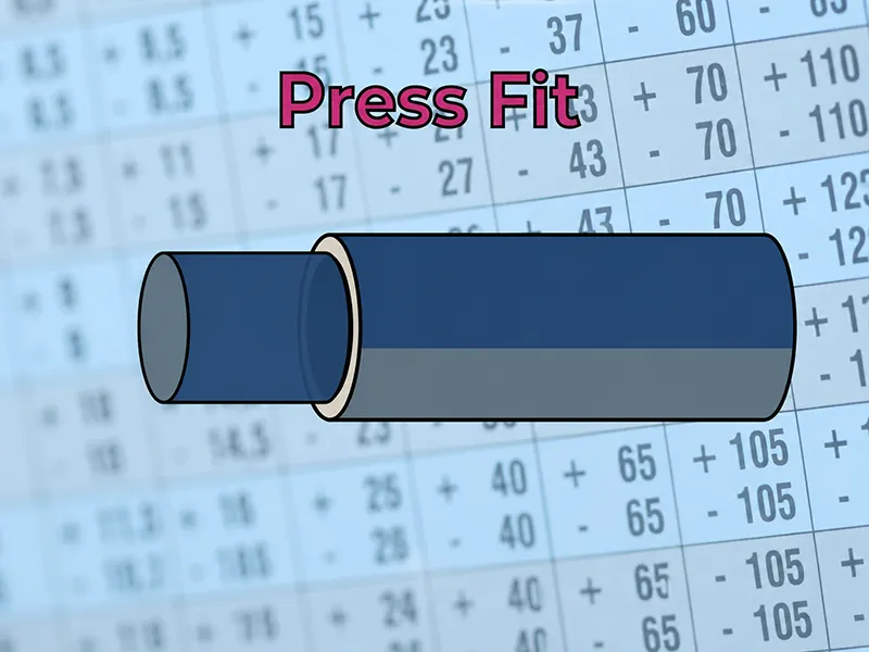
In precision CNC machining, press fit tolerance matters because an interference joint only works well when the shaft and hole are controlled as a system, not as isolated nominal dimensions. In a press fit, the shaft is intentionally made slightly larger than the mating hole, so assembly creates elastic deformation and radial contact pressure at the interface. That pressure is what helps the joint resist rotation, axial movement, vibration, and loosening in service. If the interference is too high, press force rises sharply and the hub, bearing ring, or shaft can be overstressed, distorted, or even cracked. If the interference is too low, the fit can slip, fret, vibrate, or lose retention under cyclic load. This guide explains what press fit tolerance means, how interference is calculated, how designers choose a fit, and which design, manufacturing, assembly, and inspection practices improve reliability.
What is a Press Fit?
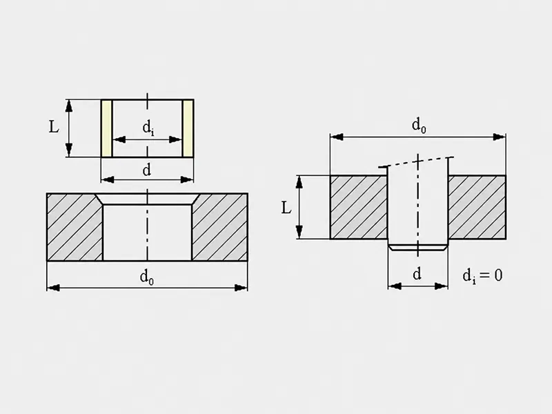
Press fit tolerance is the allowable dimensional relationship between a shaft and a mating hole that produces interference under the required fit condition. The ISO 286-1 tolerance and fit standard defines the basic concepts, terminology, tolerance classes, and principles used for basic-hole and basic-shaft fit systems; in an interference condition, the hole is smaller than the mating shaft over the intended limits. In practical terms, the largest permitted hole is still smaller than the mating shaft for the target fit range, so the assembled parts deform elastically and clamp together. Press fits are commonly used when designers want retention or torque transfer without separate fasteners, adhesives, keys, or splines.
Interference = Shaft diameter − Hole diameter
A positive result means an interference fit. A zero or near-zero result indicates a line-to-line or transition condition. A negative result means clearance. The arithmetic is simple, but the engineering decision is not: what matters is the full tolerance range, not just the nominal sizes written on the drawing.
How a Press Fit Works
A press fit works because the shaft compresses slightly and the hub or bore expands slightly during assembly. That elastic deformation creates radial pressure at the contact surface, and that pressure generates friction that resists relative motion. A useful mental model is a solid shaft inside a thick-walled cylinder: the oversized shaft pushes outward, the hub pushes inward, and the interface pressure becomes the source of holding force.
Radial Contact Pressure
Greater interference generally increases radial contact pressure, but not indefinitely or without consequence. As interference rises, assembly force and local stresses also rise, and if the material or geometry cannot remain in the elastic range, the joint can plastically deform rather than gaining useful extra retention. Published analyses of interference-fit joints show that increasing interference can raise assembly force significantly, while excessive interference may begin to create plasticization and diminishing returns in joint performance.
Axial Holding Force
For a simple cylindrical joint under approximately uniform pressure, axial holding force is often estimated from interface pressure, friction coefficient, shaft diameter, and engagement length. In simplified form, engineers commonly use F ≈ μ · p · π · d · L, where μ is friction coefficient, p is contact pressure, d is diameter, and L is engagement length. That is why a longer engagement length or higher pressure usually improves axial retention, provided the materials and assembly method can support it safely.
Torque Capacity
Torque capacity follows the same friction principle. A common simplified estimate is T ≈ μ · p · π · d · L · (d/2), which shows why torque transmission increases with higher pressure, larger diameter, and longer engagement length. This is also why large-diameter shaft-hub joints can transmit substantial torque even with moderate interference, while small parts often need tighter dimensional control to achieve the same result.
Key Factors That Affect Press Fit Tolerance
Shaft and hole diameter. A fixed interference value should not be copied from one diameter to another. Schaeffler’s fit guidance explicitly notes that fit interference or clearance depends on the specific bore diameter, and ISO 286 defines fits through tolerance classes that vary with size range rather than a single universal offset.
Material properties. Elastic modulus, yield strength, hardness, ductility, brittleness, and thermal expansion all influence fit behavior. A steel shaft in an aluminum hub does not behave like steel-on-steel because aluminum alloys expand roughly about twice as much as ferrous materials with temperature change, and the stiffness mismatch changes the pressure and deformation distribution as well.
Hub wall thickness. Thin hubs expand more easily than thick hubs, so the same diametral interference can produce very different stresses and deformation depending on wall section. Thick-walled cylinder theory and engineering references both show that hub geometry affects stress distribution, and thin-walled hubs are more vulnerable to yielding or cracking under aggressive interference.
Engagement length. Longer fits increase interface area and therefore increase potential axial holding force and torque capacity. But the same area increase also raises required press force in simplified models, which is why long press fits demand better alignment and tooling discipline during assembly.
Surface roughness. Surface condition affects both insertion behavior and final holding performance. Research on press fits shows that nominal interference and effective interference are not always the same because asperity peaks can flatten during assembly. SKF also notes that seat surface texture must be controlled, even if dimensional and geometric tolerances remain primary. Rougher surfaces can increase insertion force, while uncontrolled finishing can reduce consistency from part to part.
Operating temperature. Differential thermal expansion can either loosen or tighten a fit in service. Because aluminum expands more than steel, a steel shaft in an aluminum housing can lose interference as temperature rises and gain interference as temperature drops. This is one reason why cold mounting, hot mounting, and operating temperature must all be considered in the same tolerance study.
The practical design takeaway is simple: the strongest fit is not always the best fit. The right fit is the smallest interference range that still meets torque, axial retention, alignment, vibration, and service-life requirements with acceptable manufacturing capability and assembly risk.
How to Calculate Press Fit Tolerance
The first calculation is nominal interference:
Nominal interference = Nominal shaft diameter − Nominal hole diameter
If a shaft is 20.020 mm and the hole is 20.000 mm, then the nominal interference is 0.020 mm. This is useful for a quick concept check, but it is never enough on its own because a real press fit is controlled by tolerance limits, not just nominal values.
Calculate Minimum Interference
Minimum interference = Minimum shaft diameter − Maximum hole diameter
This is the loosest possible assembly allowed by the drawing. It is the value that determines whether the joint still has enough retention at the worst-case low-interference condition. If minimum interference is too small, a joint that looks acceptable at nominal size can still slip in production.
Calculate Maximum Interference
Maximum interference = Maximum shaft diameter − Minimum hole diameter
This is the tightest possible assembly allowed by the tolerances. It usually governs maximum press force, maximum local contact stress, and maximum risk of cracking or distortion. Designers should always check this value against assembly capability, material strength, and part geometry.
Example Tolerance Stack
For the following dimensions:
- Shaft: 20.018–20.025 mm
- Hole: 19.998–20.005 mm
The interference range is:
- Minimum interference = 20.018 − 20.005 = 0.013 mm
- Maximum interference = 20.025 − 19.998 = 0.027 mm
| Item | Minimum Size | Maximum Size |
|---|---|---|
| Shaft | 20.018 mm | 20.025 mm |
| Hole | 19.998 mm | 20.005 mm |
| Interference | 0.013 mm | 0.027 mm |
The design is acceptable only if both ends of this range are acceptable in service and in assembly. Minimum interference must still prevent slipping, while maximum interference must not produce excessive force, overstress, or damage during installation. For critical or highly loaded joints, simplified hand calculations should be backed up by thick-walled cylinder theory, vendor fit tables, or FEA.
How to Select the Right Press Fit
Define the Joint Function
Start with what the joint must actually do. A bearing seat, a gear on a shaft, a bushing in a housing, and a metal insert in plastic do not need the same fit strategy. The required fit depends on whether the joint must transmit torque, resist axial force, maintain alignment, suppress vibration, or create a permanent assembly. The SKF bearing fit selection guidance provides additional considerations for choosing shaft and housing fits according to load and operating conditions. Manufacturer fit-selection guidance for bearings makes the same point: the fit is chosen from load direction, operating conditions, and the risk of creep at the interface.
Confirm the Material Combination
Next, check the pairing itself. Steel-on-steel, steel-on-aluminum, bearing steel in cast iron, or metal inserts in plastic each respond differently because modulus, yield strength, ductility, and thermal expansion differ. A fit that is safe in steel may be too aggressive in aluminum or too unstable over temperature in dissimilar materials.
Determine the Required Fit Strength
In practice, engineers often think in terms of a lighter cold press fit, a more aggressive press fit, or a thermal shrink fit, but those labels are only shorthand. The real decision must be based on diameter, material pair, wall thickness, engagement length, operating temperature, and the actual load case, not a universal interference rule. Published analysis shows clearly that “more interference” is not a universal improvement because it can raise assembly force faster than it improves useful breakaway strength.
Choose a Tolerance System
Hole-basis systems are common because the hole can often be produced economically with standard drilling, boring, and reaming processes, while the shaft size is adjusted by turning or grinding. In the ISO system, the hole-basis reference is H, while shaft-basis uses h as the fixed reference. For new designs, hole-basis is often the most practical choice; shaft-basis can make sense when stock shafting or already-finished shaft diameters must be preserved.
Common ISO reference examples for interference conditions include H7/p6, H7/r6, and H7/s6. These are useful starting points, not universal prescriptions. Fit tables from Schaeffler and ISO-based calculators show that the interference resulting from these classes varies with size range, which is why the selected class still has to be verified against component size, material, load, temperature, and the applicable engineering standard or supplier guidance.
Best Practices for Press Fit Design
Add an Entry Chamfer
A lead-in chamfer on the shaft and the bore reduces shaving, edge damage, and assembly force spikes at the start of insertion. Bearing manufacturers recommend lead-in chamfers for easier mounting; SKF recommends a 10° to 20° lead-in chamfer, while Schaeffler guidance similarly calls for lead chamfers on shaft ends and housing bores.
Avoid Sharp Internal Corners
Shoulders and corner radii need just as much attention as diameters. If the shaft fillet or housing corner interferes with the mating part’s chamfer, the component may not seat fully or may concentrate stress at the edge. NSK troubleshooting guidance specifically identifies interference with bearing chamfers due to excessive shaft corner radius as a mounting problem.
Control Alignment
Press fitting is unforgiving of angular error. Use fixtures, guides, and rigid support so the shaft and hole stay coaxial throughout the stroke. This becomes more important as fit severity and engagement length increase. Production guidance for press-fit assembly emphasizes correct tooling and fixturing to prevent misalignment, while bearing mounting instructions also distinguish pressing from thermal methods when force would otherwise become excessive.
Provide Adequate Hub Thickness
If the hub wall is marginal, reduce the interference or increase the wall section before moving to production. Thin-walled hubs can expand permanently or crack under aggressive fits, even when the nominal interference looks modest. Hub thickness is one of the most important geometry checks in any shaft-hub press fit.
Specify Surface Finish
Do not leave the shaft and bore surface finish to chance. SKF and Schaeffler both note that seat roughness must be matched to the application, and modern metrology systems treat surface finish as a controlled, reportable specification rather than a vague shop preference. For press fits, the finish should support consistent insertion, predictable friction behavior, and repeatable effective interference.
Consider Disassembly
Before freezing the design, ask whether the joint must ever come apart. A permanent motor rotor or valve seat may justify a more aggressive fit than a serviceable housing or repairable machine element. If future removal matters, designers should favor the lightest fit that still meets function, or consider an alternate retention method. Excessive interference creates assembly and disassembly burdens that may not add proportional functional value.
Press Fit Assembly Manufacturing and Inspection
Mechanical Pressing
Mechanical pressing with an arbor press, hydraulic press, pneumatic press, or servo press is common because it is fast, direct, and easy to automate. But it also brings risk: excessive force, poor alignment, scoring, and part deformation are all possible if the fit is too tight or the load path is wrong. For bearing assemblies specifically, manufacturers stress that the force must be applied through the ring with the interference fit and not through the rolling elements, because that can damage the raceways.
Shrink Fitting and Thermal Assembly
Shrink fitting reduces required press force by changing component size temporarily instead of forcing the entire interference mechanically at room temperature. The hub can be heated, the shaft can be cooled, or both methods can be combined. The official NSK bearing mounting guidance explains both press-fit and shrink-fit methods for interference-mounted bearings and the precautions required during installation; NSK explicitly notes that interference-fitted bearings may be mounted by cooling with dry ice, and that shrink fits are widely used when large bearings would otherwise require excessive press force. Induction heating and controlled oven heating are common industrial approaches because they improve repeatability and reduce mechanical damage risk.
Thermal assembly still requires discipline. The heating process must stay within limits that avoid damaging the part, changing heat treatment unintentionally, or affecting nearby coatings, lubricants, seals, or dimensional stability. Industrial shrink-fitting guidance emphasizes controlled heating specifically to obtain expansion without changing metallurgical structure or overheating the component.
Machining the Shaft and the Hole
In production, shafts are commonly brought close to their final size through CNC turning and then, when tighter diameter, roundness, or surface-finish control is required, completed by grinding or another precision finishing process. Holes are commonly established by drilling and then improved by boring or reaming. Reaming can improve bore diameter, consistency, and surface finish when the pilot hole has been prepared correctly. Sandvik and Kennametal both position boring and reaming as precision hole-finishing processes, while hard-part turning remains a recognized route for hardened shaft features.
Measuring Press Fit Components
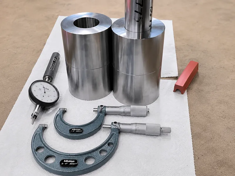
Inspection should verify more than diameter. Bore gages are widely used for close-tolerance ID measurement, while air gaging is valued for non-contact bore measurement and for assessing form on delicate or high-volume parts. CMMs are useful when the bore location, datum relationships, or feature geometry matter, and roundness or cylindricity instruments are used when form error is critical to fit behavior. Surface roughness testers add the final check on the shaft and bore finish. In other words, press-fit quality is a combination of size, form, surface, and positional accuracy, not a single diameter reading.
That is why inspection should cover the full tolerance range and the relevant geometric controls. Roundness, cylindricity, taper, straightness, and runout can all affect actual interference, assembly force, and contact pressure distribution even when the nominal diameter appears correct.
Common Problems Applications and FAQs
The troubleshooting patterns below are consistent with manufacturer mounting guidance, bearing failure analysis, and published press-fit studies: many field failures happen because teams check nominal interference only and ignore tolerance extremes, wall stiffness, geometry, surface condition, or operating temperature.
| Problem | Likely Cause | Recommended Solution |
|---|---|---|
| Shaft slips after assembly | Insufficient interference or low friction | Increase minimum interference or engagement length |
| Hub cracks | Excessive interference or thin wall | Reduce interference or increase hub thickness |
| Assembly force is too high | Excessive interference, rough surface, or misalignment | Review tolerance, finish, chamfer, and fixture |
| Shaft is scratched | Burrs, poor chamfer, or rough bore | Deburr and improve entry geometry |
| Part becomes distorted | Excessive pressure or weak geometry | Reduce interference and strengthen the hub |
| Fit loosens at high temperature | Differential thermal expansion | Recalculate fit at operating temperature |
| Bearing is damaged | Force applied through rolling elements | Press only on the correct bearing ring |
| Parts do not seat fully | Shoulder interference, geometry error, or misalignment | Add relief, verify radii/chamfers, improve tooling |
Typical Applications of Press Fits
Press fits are used across bearings in housings, bushings in bores, gears on shafts, fixture pins, motor rotors, sleeves, couplings, valve seats, tooling inserts, pulleys, and metal inserts in plastic components. What changes from one application to the next is not the principle but the required interference range. A bearing seat may prioritize creep resistance and internal clearance control, a gear hub may prioritize torque capacity, and a metal insert in plastic may be dominated by material creep and thermal behavior. The correct fit always depends on load, material, speed, temperature, and service environment.
Conclusion
Press fit tolerance controls the dimensional interference between a shaft and a hole, and that interference is what produces the radial pressure and friction that make the joint work. Minimum interference tells you whether the assembly will still resist slip at the loosest tolerance condition. Maximum interference tells you how much press force, stress, and damage risk you may face at the tightest condition. Good press-fit design therefore requires more than a nominal diameter subtraction. Engineers should evaluate the full tolerance stack together with diameter, material pair, wall thickness, engagement length, surface roughness, operating temperature, and service load. Reliable assemblies also depend on practical details such as chamfers, corner relief, alignment control, suitable assembly methods, and full inspection of size, form, and finish. The best press fit is not the tightest possible fit. It is the smallest controlled interference range that meets function without creating unnecessary manufacturing difficulty or part stress.
FAQs About Press Fit Tolerance
What is press fit tolerance
Press fit tolerance is the controlled dimensional difference between a shaft and a hole that creates interference after assembly. In an interference condition, the shaft is larger than the hole over the intended fit limits, so assembly creates elastic deformation and contact pressure.
How do you calculate press fit interference
Subtract the hole diameter from the shaft diameter. For real designs, calculate both minimum and maximum interference using the tolerance limits of both parts, because those extremes govern slip risk on one side and assembly force or overstress on the other.
How much interference should a press fit have
There is no universal value that works for every part. The correct interference depends on diameter, material combination, hub thickness, engagement length, surface finish, temperature range, and the torque or axial load the joint must resist. Fit classes such as H7/p6, H7/r6, and H7/s6 are useful references, but they still need application-specific verification.
What happens if a press fit is too tight
If a press fit is too tight, assembly force rises, contact stresses increase, and the shaft, hub, or bearing ring may deform or crack. Excessive interference can also damage rolling bearings during mounting or reduce internal clearance enough to cause hot running and early failure.

