
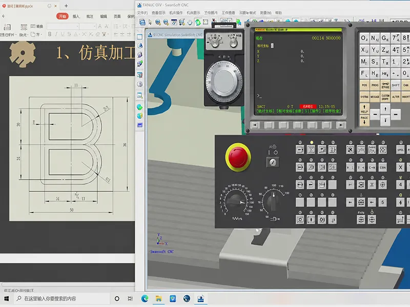
CNC machining programming is one of the biggest factors separating an average machining process from a stable, accurate, and profitable one. The program controls how a machine cuts, drills, mills, turns, and finishes a part, but the real impact goes far beyond code syntax. Toolpath strategy, work offsets, tool offsets, feed rate, spindle speed, coolant, and setup direction all influence dimensional accuracy, surface finish, chip control, cycle time, and tool life. On the other hand, weak programming and poor verification can lead to crashes, offset mistakes, chatter, bad chip evacuation, premature tool wear, scrap, and costly rework. Modern CAM software makes programming faster, but it does not replace machining judgment. To get better machining results, beginners need to learn CNC programming together with materials, cutting tools, workholding, tolerances, machine limits, and safe prove-out practices.
What Is CNC Programming
CNC programming is the process of creating the instructions that control CNC machine movement and machine functions. In practice, a CNC program tells the machine where to move, how fast to move, which tool to use, when to start the spindle, and when to turn coolant on or off. These instructions are used across milling, turning, drilling, tapping, boring, and contour machining, and they convert a digital part design into a repeatable manufacturing process. CNC machines execute these instructions through G-code and M-code, whether the program was written manually or generated from CAM software.
The most important program elements are the toolpath, coordinates, feed rate, spindle speed, tool changes, work offset, tool offset, coolant commands, and the safety lines that establish a predictable startup state. Haas programming examples, for example, show safety startup blocks that define plane selection, cutter compensation cancel, tool length compensation cancel, and work offset selection before cutting begins, followed by spindle, tool length, and coolant commands. That is why CNC programming should be understood as process planning, not just typing code.
Why CNC Programming Matters in Machining
CNC programming directly affects part quality and production efficiency because the program determines how material is removed. Toolpath decisions influence cutter engagement, entry and exit behavior, vibration, and tool deflection. Sandvik notes that unfavorable engagements and repeated entrance and exit conditions can leave marks on the surface and increase cutting-force-related tool deflection, while feed reduction in critical toolpath sections can create a safer process and longer tool life. Feed rate and cutting speed also change temperature, torque, chip formation, hole quality, and wear behavior. In other words, programming choices show up on the finished part and on the shop floor cost sheet.
Part accuracy depends on coordinate control, compensation, datum strategy, workholding stability, finishing allowance, and machine repeatability. Fusion’s setup workflow defines the Work Coordinate System as the part’s XYZ zero position, while Haas identifies tool length offset as the distance from tool tip to the top of the part, stored and called by the program. If the work origin, tool length, or compensation logic is wrong, the machine will still move exactly as programmed, just to the wrong place. Stable clamping matters too: Haas workholding guidance notes that vibration, movement, or shifting parts can hurt finish, increase tool wear, and compromise tolerance performance. Autodesk also emphasizes CNC’s strength in repeatable, consistent production once the process is correctly defined.
Programming also affects cost. CAM can reduce setup and cycle time, but only if the programmer chooses sensible operations, avoids unnecessary tool changes, uses the correct post, and validates the output. Autodesk highlights that integrated CAM can reduce setup and cycle times, while Sandvik notes that quick-change tooling reduces setup and tool change time. Inspection and part alignment tools can further reduce rework by enabling real-time adjustment before full production continues. That is why good CNC programming improves not just one part, but prototypes, low-volume jobs, and mass production alike.
Learn Basic CNC Machine Operations First
Beginners learn CNC programming faster when they understand how the machine actually cuts material. A CNC mill typically works in an X, Y, and Z coordinate system, with the XY plane defining the machining plane and Z controlling depth. Fusion’s setup documentation explains that the XY axis should lie on the machining plane while Z points away from it, and Autodesk’s coordinate-system guidance explains how CNC machines use Cartesian space and work coordinate systems to understand stock position and tool motion. Before writing or posting any program, beginners should understand machine zero, work zero, tool length offset, clamping, and the safe relationship between tool, stock, fixture, and machine travel. They should also treat dry runs, graphics mode, and single-block prove-out as part of the programming process, not as optional extras.
For CNC milling, the starting skill set is usually 3-axis work with end mills and drills. Common beginner operations include face milling to clean the top of stock, pocketing to remove material inside boundaries, slotting and groove milling, drilling cycles, and contour milling for external profiles and finishing passes. Autodesk’s manufacturing references distinguish Face, 2D Pocket, and 2D Contour as separate strategies, while Haas mill documentation lists drilling, tapping, boring, and reaming cycles as core canned-cycle functions. Learning these operations in a simple vise setup gives beginners a direct link between toolpath shape and real cutting behavior.
For CNC turning, beginners should understand spindle-driven workpiece rotation, tool orientation, and the difference between external and internal work. Autodesk’s CNC machining guide describes lathes as machines where the workpiece rotates while the cutting tool shapes it, and Haas tooling references list common turning operations such as facing, profiling, grooving, threading, parting, and internal boring. These basics matter because turning quality depends heavily on chip control, overhang, rigidity, and stable setup.
Understand G-Code, M-Code, and CAD/CAM
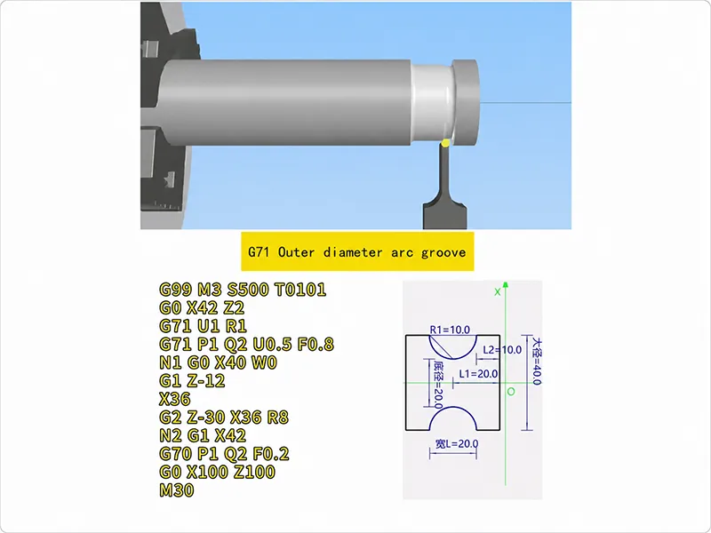
G-code is the motion language of CNC machining, and M-code handles non-motion machine functions. The official Haas mill programming guide gives practical examples of safe startup lines, work offsets, absolute positioning, spindle commands, coolant commands, and other basic CNC program structures. Haas manuals further show how these commands appear in real programs: G54 selects a work coordinate system, G43 calls tool length compensation, M03 starts the spindle clockwise, M08 turns coolant on, M09 turns coolant off, M05 stops the spindle, and M30 ends and resets the program. Beginners do not need to memorize every code, but they do need a working understanding of the codes they will see constantly in production.
A practical starter set includes G00 for rapid positioning, G01 for linear cutting, G02 and G03 for clockwise and counterclockwise arcs, G17/G18/G19 for plane selection, G20/G21 for inch or metric units, G40/G41/G42 for cutter compensation, G54 for work offset selection, and G90/G91 for absolute and incremental positioning. The corresponding M-code starter set includes M03, M04, M05, M06, M08, M09, and M30. Haas documentation also makes clear that exact code behavior can vary by machine and controller, and Autodesk warns that different brands and models often have their own “flavor” of G-code, so verification against the specific machine manual is essential.
At the same time, modern CNC programming is usually created through CAD/CAM rather than by hand-writing hundreds of lines of code. Autodesk Fusion supports 2D to full 5-axis machining, milling, turning, turn-mill, simulation, inspection, and editable post-processors in one environment. Its manufacturing references cover face milling, 2D contours, 2D pocketing, 3D pocket clearing, collision-aware simulation, setup sheets, and tool libraries, while Autodesk’s post-processor documentation explains that post files convert toolpaths into machine-specific code. The key lesson for beginners is that CAM speeds up programming and revisions, but it does not automatically choose the right stock setup, tool length, rapid path, finish allowance, or cutting strategy. Before running generated code, programmers should also confirm that the correct machine-specific post processor is used; the Autodesk Fusion Post Library is one official source for common CNC machine and control post processors. CAM outputs only become good CNC programs when the programmer understands the machining intent behind them.
Learn Feeds, Speeds, Tools, and Materials
Good CNC programming is driven by manufacturing logic, not by code alone. Sandvik’s machining formulas define spindle speed, cutting speed, feed per tooth, table feed, depth of cut, width of cut, torque, and metal removal rate as core variables in milling performance. Sandvik’s drilling guidance also shows how cutting speed affects temperature, flank wear, torque, and hole quality, while feed rate changes chip breaking, tool wear, hole quality, and time in cut. Coolant strategy matters as well because correct coolant application can reduce cutting-zone temperature and improve chip evacuation. For beginners, the point is simple: if feeds and speeds are wrong, even a perfectly formatted program can still produce bad parts.
Tool choice matters just as much. Insert geometry, nose radius, cutter diameter, flute space, overhang, and holder rigidity all influence chip formation, cutting force, vibration, and tolerance capability. Sandvik notes that chip control is a key quality factor in turning, and that poor chip evacuation and long overhangs in internal turning increase deflection, vibration, insert breakage, and poor surface finish. Haas tooling guidance likewise stresses that rigid holders reduce deflection and support tight tolerances. A beginner programmer should therefore learn to connect tool selection with operation goals: roughing needs stable material removal, while finishing needs predictable engagement, lower deflection, and better surface quality.
Material behavior changes programming strategy. In aluminum and other non-ferrous materials, Sandvik recommends sharp, positive geometries and notes that coolant is often used mainly for chip evacuation; in milling, Sandvik also warns that built-up edge and smearing can damage finish and that good chip evacuation is crucial. In stainless steels, Sandvik highlights work hardening and high cutting forces at entry, which means the toolpath and roll-in method matter. In titanium and HRSA materials, Sandvik notes high heat generation, limited cutting speed, notch wear, and edge chipping, making rigidity and controlled engagement even more important. For plastics, Harvey Performance stresses rapid heat removal to avoid melting and chip welding and notes that sharp cutting edges help reduce burr formation. Brass and similar non-ferrous alloys typically favor sharp positive tooling and controlled chip flow rather than heavy, dull cutting edges.
Practice CNC Programming Step by Step and Avoid Common Mistakes
The best learning path is progressive. Step one is reading engineering drawings well enough to understand dimensions, tolerances, datums, and design intent. Autodesk training content for practical CNC work starts with blueprint identification, GD&T symbols, datums, dimension types, and coordinate-system thinking, while ASME identifies Y14.5 as the authoritative guideline for the language of GD&T on engineering drawings and related documents.
Step two is starting with simple 2D parts. Practice facing, pocketing, slotting, drilling, external contouring, and basic turning features before moving to complex 3D forms. This lets you learn work offsets, safe retracts, cutter entry, and chip behavior without getting buried in complexity. Step three is writing small G-code programs manually so you understand safe startup lines, tool changes, work offsets, linear moves, arc moves, coolant calls, and end-of-program logic. Autodesk and Haas both emphasize that understanding G-code helps troubleshoot, validate intent, and trust the code generated by CAM.
Step four is moving into CAM for more advanced work. Build setups, define stock, choose tools, create roughing and finishing operations, post the code, and review the output. Step five is simulation and verification. Autodesk’s manufacturing simulation performs background collision checks, and Haas recommends graphics mode, dry runs, and single-block verification when proving out unfamiliar programs. Step six is safe execution: reduced overrides, operator supervision, proper setup confirmation, and inspection before committing to a full batch. Fusion’s inspection tools support probing and inspection before, during, and after manufacturing, which is especially useful for first articles and process feedback.
Many CNC programming problems blamed on “software” are really setup or process-planning errors. The table below summarizes common mistakes and better practice.
| Mistake | Possible Result | Better Practice |
|---|---|---|
| Wrong work offset | Part cut in the wrong location | Verify G54/G55 selection and WCS origin before running. |
| Wrong tool offset | Overcut, undercut, or crash | Check tool length and diameter compensation values carefully. |
| Unsafe rapid movement | Collision with fixture or part | Simulate rapids and review clearance planes before posting. |
| Incorrect feeds and speeds | Tool wear, chatter, poor finish | Match cutting data to the tool, material, and machine rigidity. |
| No finishing allowance | Poor surface accuracy | Leave controlled stock for a separate finishing pass. |
| Poor chip evacuation | Tool breakage, recutting, bad finish | Improve toolpath, coolant delivery, and chip flow. |
| Ignoring tool deflection | Dimensional error | Shorten overhang, reduce engagement, and use rigid holders. |
| Wrong post-processor | Machine alarm or unsafe motion | Use the correct machine/control post and verify output. |
| No early inspection | Scrap in batch production | Inspect the first part and feed results back into offsets or tool wear. |
The logic behind every row above is supported in official documentation: incorrect work offsets and tool length offsets are common G-code mistakes; inadequate verification and post mismatch are known failure sources; poor chip evacuation hurts tool life and surface finish; and unstable setup or long overhang can increase deflection and vibration.
How CNC Programming Improves Machining Results
Better CNC programming improves machining results because it makes the cutting process more stable. A smarter roughing path can reduce alternating cutting forces and protect the edge, while a deliberate finishing path can control stock allowance, reduce tool marks, and improve tolerance control. Sandvik’s milling guidance shows that down milling is generally preferred when the machine, fixture, and workpiece allow it because it reduces rubbing at entry, while profile-milling guidance shows that toolpath direction, engagement behavior, and feed control directly affect deflection, surface marks, and tool life. Simulation and probing further reduce crash risk and setup error before they become scrap.
For better surface finish, the programmer should think in terms of finishing allowance, steady engagement, correct stepover, sharp tools, stable feed, and coolant/chip management. Sandvik notes that climb milling reduces rubbing compared with conventional milling, and that favorable chip evacuation helps avoid scratches and poor finish. In turning and drilling, chip control remains a major quality factor because recutting chips or packing them into the cut can quickly degrade the surface.
For better dimensional accuracy, the priorities are compensation, datum strategy, fixture repeatability, thermal stability, and inspection feedback. Fusion’s probing and inspection tools are designed to align parts accurately and reduce setup errors, while Haas and Autodesk both show that work offsets, tool length offsets, and probing strategy are fundamental to where the machine actually cuts. If measured results are fed back into wear offsets or setup corrections, accuracy becomes more repeatable from one part to the next.
For lower machining cost, the gains usually come from shorter cycle times, fewer broken tools, less scrap, less rework, and smoother production flow. That is exactly why CNC programming should be treated as a machining discipline, not only as code generation. A well-programmed job does not just run; it runs predictably, safely, and profitably.
Conclusion
Learning CNC programming requires both coding knowledge and machining knowledge. Beginners should understand machine operation, coordinate systems, work offsets, tool offsets, G-code, M-code, CAD/CAM, cutting tools, feeds and speeds, workholding, materials, and safe prove-out practice. The strongest programming habits come from starting with simple parts, reading drawings carefully, writing small programs manually, using CAM for more complex jobs, simulating every setup, and verifying the first run before committing to production. When programming decisions are tied to real machining behavior, the rewards are clear: better accuracy, improved surface finish, longer tool life, shorter cycle time, and more stable production. When programming is weak, the cost shows up as crashes, scrap, rework, downtime, and avoidable tooling expense. The best way to learn is to connect every line of code and every CAM setting to what actually happens at the cutter, the fixture, and the finished part.
FAQ About CNC Programming
Is CNC programming hard to learn?
It is not hard to begin, but becoming effective takes practice with machines, tooling, materials, drawings, datums, offsets, and verification. Haas operator training and Autodesk’s practical CNC courses both treat programming, setup, safety, and inspection as connected shop-floor skills rather than isolated software tasks.
Should I learn G-code or CAD/CAM first?
The best sequence for most beginners is basic G-code first, then CAD/CAM. Autodesk explicitly notes that CAM can generate code visually without manual line-by-line programming, but also says that understanding G-code helps users debug issues, validate motion, optimize jobs, and understand post output.
Can I learn CNC programming without a machine?
Yes. You can learn coordinate systems, toolpaths, post-processing, simulation, and code review using CAM software and training content without standing at a machine. But machine-side skills such as touching off tools, setting offsets, dry running, using single block, and proving out a setup still require real equipment and supervised practice.
What is the best way to practice CNC programming?
Start with simple 2D milling or turning parts, compare the program with the drawing, simulate the toolpath, review the posted code, dry run the machine, and inspect the first part. This progression matches the way Autodesk and Haas training materials teach practical CNC workflow: drawing interpretation, setup, toolpath creation, safe prove-out, and inspection.

