
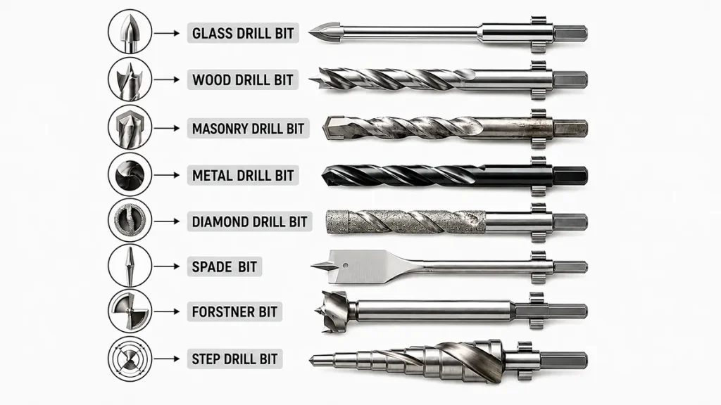
Drill size charts help engineers and machinists select the correct bit for any hole or thread. These charts cross-reference the various sizing standards (metric, fractional inches, gauge number, and letter) so you can find a nominal diameter and its decimal/metric equivalents. Choosing the proper drill size affects final hole diameter, thread quality, fit, and machining accuracy. (The nominal drill number or fraction often exceeds the finished hole once burrs and cut-over are considered.) Different hole types (clearance, tapped, dowel, blind, precision) require different selection strategies. In this guide we compare common drill standards, give tap-drill and clearance-hole tables, and explain how to pick the right bit for your application.
What Is a Drill Size Chart?
A drill size chart is essentially a reference table that shows drill diameters across multiple standards. Such charts list nominal drill sizes (e.g. “3/16 inch” or “4.2 mm”) and their decimal and metric equivalents. They often include columns for Decimal-inch Equivalent and Metric Equivalent. Many charts also add recommended tap drill sizes (for making threads) and clearance hole sizes (for bolt clearance). In practice, you look up the desired size or thread spec and the chart tells you the exact drill diameter to use. For example, a common drill chart might list “1/4 in (0.2500 in, 6.350 mm)” alongside smaller sizes like 1/16″ or larger metric sizes like 10.0 mm. By comparing the decimal equivalents, you can match inch and metric systems to the nearest available bit. In summary, a drill size chart is used to convert between measurement systems and to ensure the right drill bit is chosen for the job.
Common Metric Drill Sizes
Metric drill sizes are given in millimeters; the table below lists some commonly used metric diameters with their decimal-inch equivalents:
| Metric Size | Decimal Inch |
|---|---|
| 2.0 mm | 0.0787 in |
| 3.0 mm | 0.1181 in |
| 4.0 mm | 0.1575 in |
| 4.2 mm | 0.1654 in |
| 5.0 mm | 0.1969 in |
| 6.0 mm | 0.2362 in |
| 6.8 mm | 0.2677 in |
| 8.0 mm | 0.3150 in |
| 8.5 mm | 0.3346 in |
| 10.0 mm | 0.3937 in |
| 12.0 mm | 0.4724 in |
Note: These decimal equivalents come from exact unit conversions. For authoritative metric and inch definitions, refer to the NIST length conversion reference. For precise work, always confirm decimals (for example, 6.8 mm ≈ 0.2677″). Metric sizes follow ISO standards, but keep in mind the final hole may be slightly larger than the drill if material deflects or recovers.
Common Fractional Drill Sizes
Fractional drill sizes (the sizes in inches like 1/4″, 3/8″, etc.) are still widely used in the U.S. The table below shows a few common fractions with their decimal and metric equivalents:
| Fractional Size | Decimal Inch | Metric Equivalent |
|---|---|---|
| 1/16 in | 0.0625 in | 1.588 mm |
| 1/8 in | 0.1250 in | 3.175 mm |
| 3/16 in | 0.1875 in | 4.763 mm |
| 1/4 in | 0.2500 in | 6.350 mm |
| 5/16 in | 0.3125 in | 7.938 mm |
| 3/8 in | 0.3750 in | 9.525 mm |
| 1/2 in | 0.5000 in | 12.700 mm |
Fractional sizes are coarse (especially above 1/2″); to fill in the gaps between them, shops often use number and letter drill sizes. For example, number sizes (No. 1, 2, … 80) can drill very small holes, and letter sizes (A, B, … Z) cover in-between increments. When switching between these systems, the key is to check the decimal-inch column. That number is the true diameter, so you can match a metric drill to the fractional or number size closest to that diameter. For instance, a No. 29 drill is 0.1360″, almost exactly 3.45 mm, sitting between 3.4 mm and 3.5 mm sizes.
How to Choose the Right Drill Bit Size
Choosing the correct drill bit involves several steps to consider the hole’s purpose, material, tolerances, and subsequent operations. A systematic approach is:
- Confirm the Hole Type: Determine if the hole is a general clearance hole, a tapped hole (for threading), a blind or through hole, a dowel/pin hole, or a precision bore. * For example, a clearance hole for a bolt must be larger than the bolt’s outer diameter to allow free fit. * A tapped (threaded) hole needs a smaller pilot drill so the tap can cut full threads. * A blind hole (not through) means you must drill slightly deeper than the thread depth to allow for proper chip space (drill tip geometry often extends deeper than the thread). * A dowel hole requires a tight tolerance or press fit, often reamed after drilling.
- Read the Drawing Requirements: Check the engineering drawing or spec sheet for hole diameter (and tolerance), depth, thread callouts, position tolerance, surface finish, and any counterbore/countersink details. This tells you exactly how big the final hole must be and whether it needs threading or precision finishing.
- Check the Workpiece Material: The workpiece material (aluminum, steel, plastic, etc.) affects bit choice and drilling parameters. Harder or heat-sensitive materials need tougher bits or slower speeds. For instance, stainless steel work-hardens if drilled too fast, so use cobalt alloy bits or slow speeds with coolant. Titanium alloys cause very high heat at the drill point, often requiring carbide bits and rigid setups. Soft materials like aluminum tend to weld onto the bit and form a built-up edge (BUE), so choose sharp bits (polished or TiN-coated) and high chip evacuation strategies. Cast iron is abrasive and will quickly dull drill bits, so carbide or cobalt bits are preferred for longevity. Always adapt feed rates and coolant to manage heat and chips.
- Confirm the Final Process: Decide if the drilled hole is the end process or if it will be reamed, bored, honed, or tapped afterward. *If the hole is the final dimension and has a tight tolerance, you should leave a small allowance for finishing (reaming or honing). Drilling alone usually cannot achieve very high precision or surface finish. * For tapped holes, use the chart formula or table to pick a pilot drill size smaller than the thread major diameter (major–pitch rule). * For dowel or bearing holes, plan to drill slightly under size and then ream to the exact diameter. * For general clearance holes, the drill can be close to the fastener’s outer diameter, but often slightly oversize so the bolt slides easily.
Tap Drill and Clearance Hole Size Guide
Correct hole sizes for tapping and bolt clearance are critical for assembly fit. The tables below merge common metric thread tap-drill sizes and recommended clearance hole diameters for bolts:
Common Metric Tap Drill Sizes
| Thread Size | Common Tap Drill (Ø mm) |
|---|---|
| M3 × 0.5 | 2.5 mm |
| M4 × 0.7 | 3.3 mm |
| M5 × 0.8 | 4.2 mm |
| M6 × 1.0 | 5.0 mm |
| M8 × 1.25 | 6.8 mm |
| M10 × 1.5 | 8.5 mm |
| M12 × 1.75 | 10.2 mm |
Note: A quick rule is tap drill ≈ (major diameter – pitch) for coarse-pitch threads. For example, an M8 coarse (8.00 mm major, 1.25 mm pitch) takes a ~6.8 mm drill (8.00 – 1.25 ≈ 6.75 mm), which is exactly the charted 6.8 mm. This yields roughly 75% thread engagement. The values above target about 75% thread. In practice, you may adjust slightly (using a slightly larger drill) to reduce tapping torque and avoid tap breakage. Always double-check with the exact thread standard and material: harder materials or fine-pitch threads often require a bit larger tap drill to prevent binding.
Common Metric Clearance Holes
| Bolt Size | Close Fit (Ø mm) | Normal Fit (Ø mm) |
|---|---|---|
| M3 | 3.2 mm | 3.4 mm |
| M4 | 4.3 mm | 4.5 mm |
| M5 | 5.3 mm | 5.5 mm |
| M6 | 6.4 mm | 6.6 mm |
| M8 | 8.4 mm | 9.0 mm |
| M10 | 10.5 mm | 11.0 mm |
| M12 | 13.0 mm | 13.5 mm |
These values are based on clearance-hole standards such as the ISO 273 clearance-hole standard. A close (precision) fit keeps parts tightly located (for alignment), while a normal (free) fit allows some play. For example, an M10 bolt (10 mm major) would normally use an 11.0 mm drill for general clearance, or a tighter 10.5 mm hole if alignment is critical. When using a plate or stamping with plating or paint, add the coating thickness to the hole size or use the larger clearance. Tip: Never drill a blind hole exactly to the bolt length – add extra depth so that chips and coolant have space and full threads form at the bottom.
Choosing Drill Bits for Different Materials
Different materials demand different drill bit types and strategies:
| Material | Suggested Drill Type | Main Concern |
|---|---|---|
| Aluminum | HSS (sharp) or polished carbide | Built-up edge (chips weld to cutter) |
| Mild Steel | HSS, TiN-coated HSS, or cobalt HSS | Heat build-up; tool wear |
| Stainless Steel | Cobalt HSS or carbide | Work hardening; heat (use slow speed, coolant) |
| Cast Iron | Carbide or cobalt HSS | Abrasive wear (graphite content wears steel) |
| Plastic | Sharp HSS (brad-point or spade bit) | Melting/chipping (use low speed, backing) |
| Titanium | Solid carbide or cobalt HSS | Very high heat; rapid tool wear |
Key Tips:
- Aluminum: Is soft but gummy. It easily forms long chips and built-up edge (BUE) on the bit. Use sharp, polished bits or light coatings (TiN/DLC) to reduce sticking, and peck drill or air blast frequently to clear chips. Feed moderately – too slow or too fast both cause problems.
- Mild Steel: A common HSS bit will work, but use proper coolant/lubricant to dissipate heat. Avoid dwelling in one spot to prevent tempering the material.
- Stainless Steel: Drilling too fast heats and work-hardens the material. Use cobalt HSS or carbide bits. Drill at slow speeds with ample lubricant. Don’t pull the drill out often or it will scratch work-hardened layers, making the next pass harder.
- Cast Iron: Although brittle, cast iron contains hard graphite and silica that quickly dull cutters. A solid carbide bit or high-cobalt HSS bit is ideal. Use a slower feed and coolant through the drill if possible. Pecks are recommended to break chips.
- Plastic: Plastics melt and grab bits easily. Use a new sharp HSS or plastic-specific bit, low speeds, and backing material to prevent cracking. High speeds generate heat that melts and deforms the hole, so always slow down and have a chip evacuation path.
- Titanium: Very tough alloy – nearly impossible to drill at high speed without burning the bit. Use solid carbide or cobalt bits with aggressive coolant and a rigid machine setup. The main concern is temperature rise and rapid wear; take very light cuts and frequent pecks or use indexable carbide drills.
For deep holes in any metal, follow best practices: peck drilling or through-spindle coolant to flush chips, reduced feeds at full depth to avoid deflection, and multiple passes increasing diameter (step drilling) if needed. Always consider material-specific tooling before drilling.
When Drilling Is Not Accurate Enough
A bare drilled hole often does not meet tight tolerances or surface finish requirements. Secondary finishing operations can improve the result:
| Process | Main Purpose |
|---|---|
| Drilling | Create the initial hole (rapidly remove bulk material). Typical tolerance ±0.1–0.3 mm. |
| Reaming | Final size/finish. Brings a pre-drilled hole to exact diameter and smoother surface. Tolerance ±0.005–0.02 mm. |
| Boring | Hole enlargement/alignment. Uses a single-point cutter (boring bar) to enlarge a drilled hole, correct geometry, and improve concentricity. |
| Circular Interpolation (Milling) | High-quality hole. A small endmill is fed in a circular path (in X-Y axes) to machine a hole larger than the tool diameter; useful for large diameter holes or when only a mill is available. Allows precision size in one pass. |
| Honing | Ultra-precision finishing. Hone stones (mounted on a mandrel) are used to correct small shape errors and achieve extremely fine geometry/surface finish. Tolerances can reach a few microns. Ideal for engine cylinders or precision bearing bores. |
When to use which: Drilling gives a quick hole but only a fair surface. If the hole needs only a loose press fit or clearance (e.g. a simple bolt hole), drilling alone is often sufficient. However, locating/dowel pin holes or precision press/rolling fit shafts usually require a drilled pilot followed by reaming (or boring) for accuracy. Bearing journals and high-precision cylinders generally need drilling + boring + honing to reach the specified geometric accuracy. Always leave a small stock (e.g. 0.05–0.1 mm) for finishing tools when designing the hole.
Common Drill Size Selection Mistakes
| Mistake | Possible Result |
|---|---|
| Using thread major diameter as tap drill size | No relief for tap; likely tap breakage or incomplete threads |
| Ignoring drill runout | Oversized or tapered hole (even tiny spindle runout makes holes larger) |
| Selecting nearest drill without unit conversion | Wrong diameter; poor assembly fit or too loose/tight hole |
| Expecting drilling alone to hold tight tolerances | Hole will be out of spec or rough; functional failure on precision parts |
| Ignoring material behavior (e.g. hardening, adhesive chips) | Burrs, workhardening, melted plastic, rapid tool wear or breakage |
| Forgetting blind-hole extra depth | Insufficient full thread depth; tap may bottom out on tip |
| Ignoring plating or coating thickness | After plating, threads/bolts may not fit as drawn |
Key note: For tapped blind holes, do not drill exactly to the drawing’s thread depth. Add extra depth for the drill’s point and the tap’s lead. Typically, drill so the tip can exit slightly past the bottom of the thread, and also allow space for chip evacuation. Similarly, remember any surface coatings (paint, zinc plating, anodize) reduce effective hole diameter – either drill slightly larger or account for coating thickness in assembly.
Conclusion
Drill size charts are invaluable for comparing metric, fractional, number, and letter drill sizes and picking the right bit. They list nominal diameters with decimal and metric equivalents, simplifying unit conversions. The correct drill size depends on the hole’s purpose: clearance holes must clear the fastener, tapped holes need a smaller “tap-drill” (major minus pitch), and precision bores typically require reaming or honing after drilling. Always verify the material and tolerance: a hole in steel may need cooling and a cobalt drill, whereas aluminum needs sharp bits to avoid built-up edge. Read engineering drawings carefully for diameter, tolerance, depth, thread and surface calls. For complex or high-precision parts, consult a machinist before finalizing drill sizes.
Need Custom CNC Parts With Precision Holes? Send us your drawing, CAD model, material, hole sizes, thread specifications, tolerances, and required quantity. Our engineering team can review drill selection, tapping, reaming, boring, tool access, and inspection requirements before quotation.
FAQs About Drill Sizes
How do I choose the correct drill bit size?
Choose based on the final hole requirements: the target diameter, hole function (threaded, clearance, dowel, etc.), material, and tolerance. Check the drawing for hole size and tolerance, then pick a drill that yields the correct finished hole. If threading, use the appropriate tap drill (smaller than the bolt); if a dowel or bearing fits, plan for reaming. In short, match the drill to the hole’s spec and downstream operations (reaming, tapping).
What size drill should I use before tapping?
Use the tap-drill size for that thread, which is smaller than the thread’s major diameter. For ISO coarse metric threads, the rule is tap drill = major diameter – pitch. For example, an M6×1.0 thread (6.0 mm major, 1.0 mm pitch) uses a 5.0 mm drill (6.0 – 1.0 = 5.0). This ensures the tap can cut full threads. Do not use a drill equal to the bolt diameter – that leaves no metal to form threads and will break the tap.
Why is the drilled hole larger than the drill bit?
Several factors can make the hole oversize or out-of-round. Even small spindle runout causes the drill to “orbit” slightly, cutting a bigger hole (0.001″ runout can make a hole 0.002″ oversized). Drill bit wear and deflection also enlarge the hole. A dull or chipped drill will cut smaller at the tip but make a larger entry. Machine vibration, improper feed or speed (causing the bit to skid), and thermal expansion in the workpiece can all contribute. In short, slight runout or misalignment in the setup will produce an oversized/tapered hole.
When should a drilled hole be reamed?
Ream a hole when you need very precise diameter and a smooth finish beyond what drilling alone can achieve. If the hole requires tight tolerance (for a precise shaft or dowel fit) or an excellent surface (for bearings), drilling should be followed by reaming. Reamers are brought in after drilling (or boring) to trim away a small amount of material (~0.1–0.3 mm) and lock in the final size and geometry. In general, use drilling for roughing and reaming for finishing to spec.

