
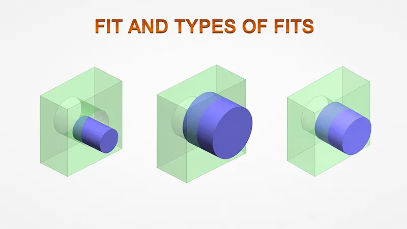
In mechanical engineering, a fit describes the dimensional relationship between two mating parts – typically a shaft and a hole – and determines how they interact. Choosing the right fit dictates whether parts rotate or slide freely, stay precisely aligned, or lock together. The three primary fit categories are clearance, transition, and interference fits. Clearance fits always have a positive gap, allowing easy assembly and movement; interference fits have overlapping tolerances, requiring force or thermal methods to assemble and creating a tight, often permanent joint. Transition fits lie between these extremes, producing either a small clearance or slight interference based on tolerances. Correct fit selection affects assembly ease, motion, alignment, load transfer, wear, and service life. Importantly, fits depend on tolerance zones (upper and lower limits of shaft and hole sizes), not just nominal dimensions. This guide explains how each fit works, its common uses, how to calculate fit limits, and practical manufacturing/inspection considerations.
What Are Fits in Engineering?
A fit defines the allowable difference (clearance or overlap) between two mating features. For example, a shaft and a hole both have specified machining tolerances, including upper and lower deviations, that determine the actual sizes. Two parts with the same nominal size can still have clearance or interference depending on these tolerances. In practice, fits are used in assemblies like bearings, gears, bushings, pulleys, dowel pins, shafts, housings and precision components. The nominal size is the basic design dimension, while the upper and lower deviations and tolerance define the allowable variation. Key terms include allowance (the intended minimum clearance or interference) and clearance/interference (the actual gap or overlap). By selecting the appropriate fit (via standard notations like H7/h6, etc.), engineers control whether parts slide, fit snugly, or lock.
Why Are Engineering Fits Important?
The chosen fit determines how components perform under load and motion. For example, a rotating shaft in a bearing needs enough clearance to allow lubrication and prevent binding, whereas a shaft gear or bearing race may need an interference fit to stay fixed under torque and vibration.Proper fit selection prevents excessive looseness, vibration, noise or part movement, and avoids difficult assembly or damage. Good fits also maintain alignment and positional accuracy in assemblies (critical in robotics, automotive, aerospace, etc.) and affect friction, wear, lubrication and heat generation during operation. Choosing the wrong fit can cause shaft slippage, bearing wobble, seizure, cracking or premature wear. For example, bearing journals often use interference fits for high-load retention, while guide rails use clearance fits for smooth sliding.
The Three Main Types of Fits
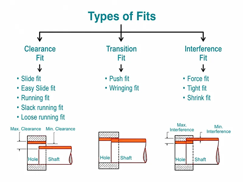
The classification of a fit depends on the relative tolerance zones of the hole and shaft:
- Clearance Fit: Hole tolerance zone is entirely above the shaft zone (smallest hole > largest shaft). There is always some positive gap after assembly, allowing free movement.
- Transition Fit: Hole and shaft tolerance zones overlap. Assembly can result in either a small clearance or a small interference depending on actual sizes. It provides precise location but parts can still be disassembled if needed.
- Interference Fit: Shaft tolerance zone is entirely above the hole zone (shaft is always larger). Parts must be pressed or heated/cooled to assemble, creating a tight friction fit with no play.
Figure: Tolerance-zone diagram illustrating clearance (left), transition (center), and interference (right) fits.
In a clearance fit, every assembled pair has positive clearance (gap). In a transition fit, the clearance may be zero or a small overlap. In an interference fit, the assembled shaft must deform the hole (or vice versa), generating force-lock.
What Is a Clearance Fit?
A clearance fit is the most common type, where the hole is always slightly larger than the shaft. This guarantees a gap between the parts after assembly. The clearance allows free movement (sliding or rotation) without binding, controlled by the components’ tolerances to avoid excessive looseness. In other words, the minimum clearance (smallest hole minus largest shaft) is always positive.
Common Types of Clearance Fits
Clearance fits come in several grades (from loose to tight):
- Loose Running Fit – Very large clearance for very easy assembly. Used where accuracy isn’t critical (e.g. pivots, latches, parts exposed to dust or deformation).
- Free Running Fit – Generous clearance suitable for lightly loaded shafts (e.g. lubricated bearings, sliding shafts).
- Close Running Fit – Smaller clearance for moderate-speed rotating shafts (machine-tool spindles, slide rods) where some precision is needed.
- Sliding Fit – Very tight clearance; parts can still slide/turn easily. Used in high-precision slides, guides, and valve assemblies.
- Locational Clearance Fit – Minimal clearance for accurate locating; parts can be assembled by hand and still rotate freely with lubrication (e.g. precision guides, dowel holes).
Example Codes: ISO fits like H11/c11 (loose), H9/d9 (free), H7/g6 (sliding), H7/h6 (locational clearance).
Common Applications of Clearance Fits
Clearance fits are ideal where movement or easy assembly is required. Examples include: bearings (allowing shafts to rotate freely), sliding guides and linkages, removable covers and panels, bolts in holes, and parts requiring lubrication or frequent disassembly. For instance, plumbing fittings and pipe couplings use clearance so parts can slide together easily.
Advantages and Limitations
- Advantages: Easy, damage-free assembly and disassembly. Supports rotation and sliding. Allows for lubrication films and tolerates thermal expansion. Lower machining stress and risk of jamming.
- Limitations: Less precise location of parts. Potential for vibration, rattle, or noise if clearance is excessive. Wear can increase clearance over time, reducing accuracy. Not suitable for transmitting high torque or heavy loads without additional fasteners.
What Is a Transition Fit?
A transition fit falls between clearance and interference fits. The hole and shaft tolerances partially overlap, so the assembled pair may have either a small clearance or a slight interference depending on the actual sizes. In practice, a transition fit often yields a very snug fit with either no gap or a light press required. It provides more accurate location than a loose clearance fit but is still not permanently locked.
For example, a transition fit (such as ISO H7/k6 in a hole-basis system) can give up to ~0.02 mm clearance or ~0.02 mm interference. Assembly usually requires hand pressure or light tapping (a rubber mallet is often sufficient for a “similar fit”).
Common Types of Transition Fits
ISO transition fits include:
- Similar (Locational) Fit: Negligible clearance or interference. Can usually be assembled/disassembled with gentle force (e.g. rubber mallet). Used for gears, pulleys, and hubs. (Hole basis ex: H7/k6.)
- Fixed (Push) Fit: Small interference or minimal clearance. Requires light pressing during assembly. Used for plugs, driven bushes, armatures on shafts. (Hole basis ex: H7/n6.)
Example Codes: H7/k6 (light transition), H7/n6 (small interference).
Common Applications of Transition Fits
Transition fits are used where precise alignment is needed but parts still may be removed. Typical examples: gears or pulleys on shafts (for accurate positioning with a light press), couplings, dowel pins, and precision housings. Machine tool fixtures and precision engine components often use transition fits for repeatable location. Bearings can use transition fits when slight movement control is needed without full locking.
Advantages and Limitations
- Advantages: Provides good positional accuracy with minimal play. Supports light torque transfer. Parts can still be disassembled (unlike interference fits). Ideal for precision assemblies where tight clearance is needed but removal might be required later.
- Limitations: Actual result (clearance or interference) can vary within tolerance range. May require controlled force (press or mallet) to assemble. Sensitive to machining variation and surface finish – a slight error could shift from clearance to interference.
What Is an Interference Fit?
An interference fit (also called a press fit or force fit) occurs when the shaft is always larger than the hole. In this case, assembly requires the parts to deform slightly or be pressed together, creating a tight, friction-locked joint. For example, a shaft might be heated or a hole cooled (shrink-fit) to ease assembly. Once mated, an interference fit transmits torque and axial loads without additional fasteners.
Figure: Example of an interference fit – a gear or bearing pressed onto a shaft.
Common Types of Interference Fits
Typical interference categories include:
- Press (Light Drive) Fit: Small interference requiring cold pressing. Used for moderate-lock applications (e.g. press-fit bushings, collars). (ISO example H7/p6.)
- Driving (Medium Drive) Fit: Moderate interference requiring significant press or mild heating. Used for tighter press-fit parts (e.g. permanent gear/shaft mounts, motors). (ISO H7/s6.)
- Shrink (Heavy/Force) Fit: Large interference that generally requires thermal methods (heating/cooling). Used for permanent connections that should not be disassembled (e.g. high-torque couplings, locked gears). (ISO H7/u6.)
Common Applications of Interference Fits
Interference fits are used when components must remain fixed under load or stress. Common examples include: pressing bushings or sleeves into housings, mounting gears and pulleys on shafts, securing bearing races to prevent rotation, and fitting wheel hubs or rotors on axles. Essentially, any assembly that must transmit high torque or resist axial loads without a key or bolt may use an interference fit.
Advantages and Limitations
- Advantages: Very strong retention and precise positioning. No need for additional fasteners (fewer parts). Excellent torque and load transfer (ideal for rotating machinery and permanent joints).
- Limitations: Assembly usually requires special equipment (press, heating, cooling). Disassembly is difficult or destructive. Excessive interference can crack or distort parts. High friction on assembly; surface damage (brinelling) can occur if not done carefully.
Clearance vs Transition vs Interference Fit
| Fit Type | General Condition | Typical Function |
|---|---|---|
| Clearance fit | Hole always larger than shaft | Rotation or sliding; easy assembly and removal |
| Transition fit | Tolerance zones overlap (may barely clear or interfere) | Accurate location with light press possible |
| Interference fit | Shaft always larger than hole | Permanent, high-strength joint; torque transmission |
In summary, clearance fits allow movement and simple assembly, transition fits provide precise alignment with limited clearance, and interference fits create rigid, permanent connections. Designers choose the loosest fit that still satisfies functional requirements to balance performance and cost.
Understanding Hole and Shaft Tolerance Zones
When designing a fit, the actual clearance or interference is determined by the tolerance limits of each part. For a given nominal size, each feature has a maximum and minimum dimension. For example, if a 50.00 mm hole has a tolerance of +0.02/0.00 mm and a 50.00 mm shaft is –0.00/–0.01 mm, then:
- Maximum Clearance: (Largest hole) – (Smallest shaft).
- Minimum Clearance: (Smallest hole) – (Largest shaft).
- Maximum Interference: (Largest shaft) – (Smallest hole).
- Minimum Interference: (Smallest shaft) – (Largest hole).
Using these formulas, one can calculate the potential range of clearance or overlap. For instance, if the hole is 50.020 mm max and 50.000 mm min, and the shaft is 49.990 mm max and 49.980 mm min, then maximum clearance is 50.020 – 49.980 = 0.040 mm, and minimum clearance is 50.000 – 49.990 = 0.010 mm. If the shaft were larger, some or all of this clearance range would turn into interference. In other words, fits depend on the tolerance zones of hole (letter code, e.g. H7) and shaft (e.g. h6) rather than nominal size alone.
Hole-Basis System vs Shaft-Basis System
Standard fits are usually specified using either a hole-basis or a shaft-basis system:
- Hole-Basis System: The hole size is held at the fundamental (basic) dimension, and the shaft tolerance is adjusted to achieve the desired fit. In practice, engineers often fix the hole tolerance (e.g. H7) and machine or grind the shaft to match. This is convenient because making holes with standard drills/reamers is simple, and shafts can then be produced precisely to size.
- Shaft-Basis System: The shaft size is held at the basic dimension, and hole tolerance is adjusted for fit. This is used when standard shaft stock or pins must be used. For example, if using pre-ground shafts or dowel pins (with fixed tolerances), one can size the hole accordingly. It is less common in general practice but used in some applications (like standard bearing shafts).
In summary, the hole-basis system keeps the hole dimension constant and varies the shaft, while the shaft-basis system does the opposite. The hole-basis approach is widely used in machining since standard tooling makes hole sizes predictable.
Hole-Basis System
In a hole-basis system, the hole’s tolerance position (letter/grade) is fixed (often an “H” tolerance in ISO), and the shaft tolerance is chosen relative to it. For example, an H7 hole may mate with a g6, h6, or n6 shaft to create clearance, transition, or interference. This convention simplifies design: engineers select a standard hole and then specify the appropriate shaft tolerance.
Shaft-Basis System
Conversely, in a shaft-basis system the shaft tolerance is fixed (often an “h” tolerance) and the hole tolerance varies. This is useful when the shaft dimension comes from standard stock (such as precision-ground rods). The hole is then bored or reamed to either a smaller or larger tolerance zone to produce the needed fit.
How to Read ISO Fit Designations
ISO fit codes like H7/g6 or H7/k6 consist of a letter or letters and a number for both the hole and shaft. The letter, such as H, g, or k, indicates the tolerance-zone position relative to the basic size, while the number, such as 6 or 7, indicates the tolerance grade or IT grade. Upper-case letters (A, B, C, …, H, etc.) normally denote holes, and lower-case (a, b, c, …, h, etc.) denote shafts. For example:
- H7/h6: A common close running clearance fit. “H7” means the hole tolerance starts at zero (no oversize) and extends +0.021/0.000 mm for a 25 mm hole (example); “h6” means the shaft tolerance ends at zero and extends –0.006/0.000 mm. So smallest hole = 25.000, largest shaft = 24.994; minimum clearance = 0.000, max = 0.027 mm.
- H7/k6: A light transition fit. The hole (H7) is the same as above, but shaft “k6” means the shaft is slightly oversized (+0.002/+0.018 mm for 25 mm). This yields a very small clearance or slight interference (assembly by mallet).
- H7/p6: An interference fit (press fit). Here the shaft “p6” tolerance is larger still (+0.026/+0.042 mm), so the shaft is always bigger than the hole; assembly requires pressing or heating.
Always refer to ISO 286-2 or another applicable fits and tolerances standard to determine the exact limit deviations for a given code, because the numerical values depend on the nominal size range. The letter indicates the position of the tolerance zone relative to the basic size, while the number indicates the tolerance grade. Smaller IT numbers (e.g. 6 vs 7) mean tighter (smaller) tolerances.
Common Fit Classes and Their Applications
| Fit Category | Tolerance/Allowance | Typical Applications |
|---|---|---|
| Loose Running Fit | Largest clearance (e.g. H11/c11) | Non-critical clearances; contaminated environments; hinges, latches. |
| Free Running Fit | Moderate clearance (e.g. H9/d9) | Light-speed shafts with lubrication (plain bearings, low-speed gears). |
| Close Running Fit | Smaller clearance (e.g. H8/f7) | Precision guide rods, machine tool spindles, moderate loads. |
| Sliding Fit | Tight clearance (e.g. H7/g6) | Linear guides, sliding mechanisms, parts requiring high accuracy. |
| Locational Clearance Fit | Minimal clearance (e.g. H7/h6) | Precision locations (dowel pins, snug-fitting bushings) where parts still move freely. |
| Locational Transition Fit | Very small clearance or slight interference (e.g. H7/k6) | Gears, pulleys, or couplings needing exact location with light press assembly. |
| Light Press (Interference) Fit | Small interference (e.g. H7/p6) | Press-fit bushings, collars, and parts where a gentle press locks them. |
| Medium Press Fit | Medium interference (e.g. H7/s6) | Shrink-fit sleeves, permanent mounts for moderate loads (bushings, collars). |
| Heavy Interference Fit | Large interference (e.g. H7/u6) | Permanent assemblies (locked gears, flywheels, heavy-duty couplings). |
Each class has a typical assembly method: Loose/free running fits are assembled by hand or simple alignment; locational fits may need light taps; interference fits often require hydraulic presses or thermal assembly. The table above gives a sense of the tolerance condition and common uses of each fit class.
Factors to Consider When Choosing a Fit
Engineers must balance many factors when selecting a fit:
- Movement Requirement: Does the part need to rotate or slide? For free movement (bearings, shafts) choose a clearance fit. For a fixed, non-moving joint choose an interference fit. Transition fits serve where limited movement or slight flex is acceptable.
- Positional Accuracy: How tightly must parts be located? Higher precision assemblies (machine tools, instruments) often use tighter fits (locational clearance or light transition) to minimize play.
- Load and Torque: High loads or torques call for interference fits (e.g. gears, bearings under load) to prevent slippage. Lightly loaded parts can use clearance or transition fits.
- Operating Speed and Wear: High-speed shafts usually need clearance for lubrication; slow or oscillating parts can use tighter fits. Remember that wear in a clearance fit will increase clearance over time.
- Thermal Expansion: Different materials expand differently. For example, aluminum’s thermal expansion (~23×10⁻⁶ /°C) is roughly double steel’s (~12×10⁻⁶ /°C). In an aluminum housing with a steel shaft, rising temperature can reduce clearance or even cause interference. Design clearances must account for operating temperature ranges. Similarly, plastic parts may creep or swell with humidity.
- Material Selection: Soft or ductile materials (aluminum, brass, plastic) may not tolerate high interference because they deform or strip. Harder materials (steel alloys, titanium) can take tighter interference. Softer materials may need looser fits or threaded inserts for durability.
- Manufacturing Capabilities: Tight fits require precise machining and inspection. Make sure the chosen tolerances match your machine accuracy and tooling (drills, boring bars, grinders). For example, achieving a very tight fit may require grinding or honing rather than just drilling.
- Cost and Volume: Tighter tolerances and more precise fit classes are generally more expensive to machine and inspect. For example, a higher-grade ISO tolerance (lower IT number) increases machining time and scrap risk. Large production runs may amortize these costs, but prototypes or small batches may favor easier fits. Always use the loosest fit that satisfies function to save cost.
- Assembly and Maintenance: If the joint will be disassembled (maintenance, replacement), avoid very high interference fits. Clearance or light transition fits allow easier servicing. Also, consider adding chamfers and specifying surface finish to aid assembly and reduce risk of galling.
In short, a tighter fit is not always better. The loosest fit that meets functional needs is usually the most cost-effective and reliable.
How Materials and Temperature Affect Fits
Operating conditions can change fits in service. Common considerations include:
- Thermal Effects: Heating a part causes it to expand. For example, if a hot engine block expands more than its steel bearings, clearances shrink, risking seizure. Conversely, cooling a press-fit steel shaft in a frozen state can make assembly easier (shrink-fit). In assemblies combining different materials (steel shaft in aluminum bore), temperature rise can turn a small clearance into interference. Always account for coefficients of thermal expansion when tight tolerances are critical.
- Material Hardness and Treatment: Surface hardness or treatments (carburizing, nitriding) can slightly change dimensions or induce stress. Machining before heat treatment might cause final warping. In many cases, critical fits are machined after heat treatment or uses allowances for distortion.
- Creep and Moisture (Plastics): Thermoplastics (nylon, POM, etc.) absorb moisture and creep under load. A tight fit in a plastic part may loosen over time. For plastic-metal fits, designers often oversize holes or use inserts to compensate for these effects.
- Thin-Walled Parts: Very thin housings can deform when pressed. A thin aluminum housing may buckle slightly under press fit, loosening the interference. Designs should ensure sufficient wall thickness or use support mandrels during assembly.
Surface Finish and Geometry Requirements
Fit performance depends not only on diameter tolerances but also on surface quality and shape:
- Surface Roughness: Rough surfaces increase friction. Peaks may wear off, effectively enlarging the gap after a few cycles. Specify a finish (Ra) where needed; for press fits, slightly rougher surfaces can actually improve grip.
- Roundness and Cylindricity: If a hole or shaft is out of round, some portions may have greater interference while others may have clearance. Excessive runout can also cause uneven loading. Appropriate GD&T controls, such as circularity, cylindricity, and runout, help ensure that mating surfaces create a consistent fit around their circumference.
- Straightness/Perpendicularity: A tapered or crooked bore may require much more force to insert a shaft in one direction than another. Chamfers on edges are essential to guide shafts into holes and prevent edges from digging in.
- Burrs and Debris: Sharp edges or burrs can block assembly or scratch surfaces. Always deburr and clean mating parts. Even a small nodule on the hole edge can create a false interference.
- Lubrication: Design assembly procedures and tolerances with lubrication in mind. A lubricated shaft needs less force, effectively slightly increasing clearance during assembly.
In summary, specify necessary geometric tolerances (roundness, straightness, etc.) and finishes when designing critical fits. These measures ensure the actual fit behaves as intended, not spoiled by out-of-shape or rough surfaces.
Manufacturing Methods for Fit-Critical Parts
Producing parts that meet tight fit tolerances typically involves the following processes:
CNC Turning
CNC turning is used for shafts and cylindrical parts and can achieve precise diameters, concentricity, and surface finishes in one setup. Stepped shafts with multiple diameters and bearing seats are commonly machined on lathes. Final finishing passes or grinding can bring the diameter to specification.
CNC Milling and Boring
Holes in blocks, plates, and frames are often made by CNC milling or drilling, then boring to finalize size. Boring enlarges and refines a drilled hole for better alignment and roundness. On a milling machine, a bored hole can reach tight size and positional tolerances.
Reaming
After drilling or boring, reaming is used to achieve a precise final diameter and smooth surface. Reamers remove a small amount of material to produce a finely finished hole. For example, a properly reamed hole may be used to meet an ISO H7 tolerance for applications such as bearings or dowel pins. Typical achievable accuracy is on the order of ±0.005 to ±0.02 mm with good finish.
Grinding
For very tight tolerances (often in hardened parts), cylindrical grinding (for shafts) or surface/grinding out holes is used. Grinding can achieve micron-level accuracy and very fine finishes on hardened steels and alloys. Bearing journals and hardened shafts are frequently ground to final size.
Honing
For ultra-precise bores (e.g. hydraulic cylinders, engine liners), honing may be applied. Honing improves roundness and finish of deep holes that are difficult to drill/ream accurately. It also removes minor scale or hard spots, producing extremely smooth bores.
Each method can be combined: e.g., drill → bore → ream for a final pin hole. Always ensure sufficient stock allowance for finishing, and use stable fixturing to avoid chatter. For long or deep holes, specialized long reamers or guided drilling may be needed. DFM Note: Avoid specifying extremely tight tolerances unless required; each additional finishing step adds cost and lead time.
How Fits Are Measured and Inspected
Accurate inspection is key to ensuring fits meet specifications. Common measurement methods include:
- Plug Gauges: Go/No-Go plug gauges quickly check hole diameters. A Go plug verifies the minimum hole size, and a No-Go plug confirms the hole is not too large. Similarly, ring gauges check external shaft sizes. This is a quick shop-floor method for pass/fail tests.
- Calipers and Micrometers: Precision digital calipers or micrometers measure external diameters and simple dimensions. However, they may not capture form errors.
- Bore Gauges: Telescoping or dial bore gauges can measure hole size to ±0.01 mm accuracy. Indicators on stable blocks give diameter readings after calibration.
- Coordinate Measuring Machines (CMM): For high-precision parts, a CMM can probe multiple points on the hole and shaft to determine true dimensions, roundness, and position. CMM reports can verify that all size and positional tolerances (including concentricity and perpendicularity) are met.
- Optical/3D Scanning: Laser scanners or vision systems can non-contact inspect profiles, useful for large or delicate parts.
- Surface Finish Measurement: Profilometers measure Ra or Rz of mating surfaces, which can affect fit as discussed above.
Note: Always perform measurements at a controlled temperature (typically 20°C) to avoid thermal expansion errors. Record actual measurements and compare to the tolerance limits calculated from the ISO/ANSI standard or drawing.
Common Fit Design and Manufacturing Mistakes
| Problem | Cause | Solution |
|---|---|---|
| Selecting fit by nominal size only | Ignoring tolerance ranges | Always calculate clearance/interference from tolerance limits. Use standard fit tables. |
| Ignoring surface finish or burrs | Increased friction or binding | Specify finish; remove burrs and deburr parts. |
| Overlooking thermal effects | Fit changes during operation | Account for expansion; use shrink-fit if needed. |
| Excessive interference | Hard assembly or part damage | Reduce interference; consider intermediate transition fit. |
| Too little clearance (no lubrication space) | Parts seize or gall on assembly | Ensure minimum clearance plus lubrication. |
| Overly tight tolerances | Higher machining and inspection cost | Only specify tight tolerance if functionally needed. |
| Neglecting roundness/cylindricity | Uneven contact, high stress points | Add GD&T controls (roundness, cylindricity) as required. |
| No chamfer on press-fit hole | Edge damage, difficult assembly | Add chamfers or lead-ins on holes/shafts. |
| Using permanent fit for serviceable assembly | Cannot disassemble | Use a clearance or transition fit (and/or key) instead. |
Avoid these pitfalls by proper Design for Manufacturing (DFM) review. For example, specify chamfers on shafts (e.g. 30° chamfer) to guide it into a press-fit hole and prevent edge-lock. If a fit must be very tight, consider a trial with a prototype to ensure feasibility. Also, do not assume a tighter fit is stronger—sometimes a slightly looser fit with a set screw or key is more practical.
Assembly Methods for Different Fits
- Clearance Fits: Parts can be assembled by hand or simple sliding. Light lubrication (oil or grease) often helps. If alignment is tricky, gently rotating the shaft or using slight tap with a mallet can seat the parts. No special equipment is required for light fits.
- Transition Fits: Can often be assembled with moderate force. Hand pressure may suffice for loose transition fits. A soft mallet or hammer can tap parts together. A small press (arbor or hydraulic) may be used. Always align parts carefully to avoid skewed insertion.
- Interference Fits: Require more force. Common methods include using a hydraulic or arbor press. Thermal assembly is frequent: heat the outer part in an oven or torch to expand it, or chill the inner part in dry ice to contract it, then fit together. After parts return to ambient temperature, the interference locks them. In production, induction heating can rapidly expand the hole. Always support components to prevent bending and lubricate suitably (dry-film or grease) during pressing. Safety Tip: For bearings, do not apply force through rolling elements – drive on the ring or use a sleeve. Monitor press force and stop before part distortion.
Fit Selection Examples
- Rotating Shaft in a Bushing (Bearing): A clearance fit is usually chosen for the shaft inside a bushing or bearing to allow rotation. For example, an H7/g6 fit (sliding fit) is common for light- to medium-duty bearings.
- Dowel Pin Locating Plates: One side of the pin may use a transition fit (press-fit) into a plate for a precise stop, while the other side uses a clearance fit so the mating plate can be removed. For example, a fixed dowel on one part and a loose hole on the other.
- Gear Mounted on a Shaft: Typically an interference (press) fit to prevent slipping under torque. A light press fit (e.g. H7/p6) or shrink fit (heat the gear, slide on shaft) is used. Often combined with a key or spline for high torque.
- Removable Pulley on a Motor: Often a transition or light interference fit on the shaft, plus a set screw or key. For example, H7/k6 (transition) allows a snug fit that can still be removed with moderate effort.
- Bearing Outer Race in a Housing: Usually an interference fit so the race won’t spin in the housing under load. A light or medium press fit (H7/p6 or H7/n6) is common, chosen based on operating temperature and load. In some high-speed or high-temperature cases, a locational clearance fit (with clamps) might be used instead.
Cost Considerations for Precision Fits
Fit specifications can significantly impact manufacturing cost:
- Quantity of Fits: More holes or shafts with tight tolerances add machining time.
- Tolerance and Fit Class: Tighter tolerances (lower IT grade) often require slower feeds, more passes, and additional finishing (e.g. grinding, honing). This drives up cost.
- Hole Depth: Deep blind holes or long shafts are harder to finish; more expensive tooling is needed.
- Surface Finish and Treatment: Requirements like fine finishes, coatings or heat-treating add cost.
- Material: Hard or exotic materials take longer to cut.
- Special Operations: Press-fitting (especially with heating or fixturing), inspection (CMM reports), and assembly aids (chamfers, lubricants) all add to labor.
- Rework Risk: Very tight interference fits risk part damage or scrap if done incorrectly.
To minimize cost, avoid specifying deep threads or extremely tight fits unless necessary. A loose-fit design with extra fasteners can be cheaper than a machined press-fit. As noted above, “tight tolerances are more expensive to achieve”. In practice, the functional requirements should justify any precision that increases cost.
How to Choose the Right Type of Fit
A simple decision process:
- Define Movement Needs: If parts must rotate or slide freely, start with a clearance fit. If they must stay fixed under all conditions, start with an interference fit.
- Set Accuracy Requirements: Higher location accuracy (critical alignment) may push you toward transition or tight clearance fits.
- Determine Load and Torque: Heavy or shock loads favor interference. Light loads may only need clearance or transition.
- Consider Removability: If maintenance or disassembly is required, avoid permanent interference fits.
- Check Materials and Environment: Account for thermal expansion differences and material softness.
- Pick Fit Category: Based on above, choose clearance, transition, or interference.
- Select Tolerance Grades: Use ISO/ANSI tables to find the hole (e.g. H7) and shaft (e.g. h6, g6, k6, p6) that give the desired allowance.
- Verify Manufacturing: Ensure machines and gauges can achieve the tolerance.
- Prototype/Test: Where critical, make a test piece to check assembly and performance.
This approach ensures the chosen fit matches the real-world functional and manufacturing constraints of the design.
Conclusion
Clearance fits always leave a gap (hole larger than shaft) so parts slide or rotate easily. Transition fits may leave a small gap or require a light press; they offer precise location with limited movement. Interference fits require force or thermal methods to assemble; the parts overlap and form a rigid, high-strength joint. Proper fit selection considers the actual tolerance zones of hole and shaft, not just nominal sizes. Designers must account for material properties (hardness, thermal expansion), operating conditions, surface finish and required precision. Unnecessarily tight fits increase machining and inspection cost, so the best practice is to use the loosest fit that meets functional requirements. In every case, review the fit in the design phase (DFM) and plan for appropriate machining and inspection. By doing so, you ensure reliable assemblies with optimal performance and cost.
FAQs About Types of Fits
What are the three main types of fits?
The three main fit categories are clearance, transition, and interference fits. A clearance fit always has a positive gap (hole larger than shaft) allowing free movement. A transition fit’s tolerances overlap slightly so assembly can result in either a tiny clearance or slight interference. An interference fit always forces the parts together (shaft larger than hole), requiring pressing or heating and producing a locked joint.
What is the difference between clearance and interference fit?
In a clearance fit, every assembled pair has some space between the parts – the smallest hole diameter is larger than the largest shaft. Parts can be assembled by hand and can move (slide or rotate) freely. In an interference fit, the shaft is always larger than the hole (even at minimum dimension), so the parts must be forced together under pressure or via thermal expansion. This creates a tight, often permanent joint that transmits torque and axial loads.
What is a transition fit used for?
A transition fit is used when precise alignment is needed without permanently locking the parts. It’s ideal for assemblies that require a tight location but may need disassembly later. For example, mounting a gear or a pulley on a shaft often uses a transition fit so the component is snug (minimal play) yet still removable with a light press or mallet.
How do you calculate the clearance or interference of a fit?
Calculate clearance and interference from the extreme sizes:
Maximum clearance = (Largest hole size) – (Smallest shaft size).
Minimum clearance = (Smallest hole) – (Largest shaft).
If these formulas yield a negative value, it is interference. For interference: Maximum interference = (Largest shaft) – (Smallest hole).
Minimum interference = (Smallest shaft) – (Largest hole).
These calculations use the actual upper/lower limits of the hole and shaft tolerances, not just nominal size.
Which fit is best for bearings?
Bearing fits depend on the load direction, operating conditions, bearing size, shaft material, housing material, and whether the bearing ring rotates relative to the load. The manufacturer’s bearing fit recommendations should therefore be checked before selecting the shaft and housing tolerances. Depending on the application, a bearing ring may require a clearance, transition, or interference fit. However, some bearings (especially in high-speed or serviceable applications) use a transition or locational clearance fit to allow easier assembly and lubrication. Always follow the bearing manufacturer’s recommendation and consider load direction, temperature, and lubrication when choosing the fit.
Why do tight fits increase machining cost?
Tighter fits require more precise machining and quality control. Achieving a smaller tolerance band often means slower feed rates, additional finishing steps (like grinding or honing), and more frequent tool changes. It also means more inspections and potential scrap if parts fall outside tolerance. In practice, “tight tolerances are more expensive to achieve”. If a function doesn’t truly require extreme precision, specifying a looser tolerance and fit can significantly reduce machining time and cost without compromising performance.

