
Datums are the quiet foundation under almost every good engineering drawing. They are what let a designer define where a feature should exist in space, how a machinist should set a part up, how an inspector should align it, and how an assembly team can expect one part to fit another without guessing. The American Society of Mechanical Engineers describes GD&T as a common language for product realization, while the International Organization for Standardization states that ISO 5459:2024 specifies the terminology, rules, and methodology for datums and datum systems in technical product documentation. That is why datums matter far beyond drafting alone.
This guide explains what a datum is, how it differs from a datum feature, the main datum types, how datum references work on drawings, how datums control location and orientation in GD&T, and why good datum selection affects CNC machining, fixturing, inspection, and assembly. It also addresses the misunderstandings that most often create ambiguity, unstable setups, or expensive measurement disputes.

What Datums Are
At the most practical level, a datum is a reference used for processing or measuring a part. A practical summary from KEYENCE defines a datum as a plane, straight line, or point used as a reference when processing a material or measuring a target. Technical work from the National Institute of Standards and Technology adds the deeper metrology point: given an imperfect datum feature on a real workpiece, the datum is a mathematically perfect geometry associated with that feature. In other words, the datum is exact even when the part is not.
That distinction is what makes datums so important in engineering drawings. NIST notes that datums are used extensively to locate and orient tolerance zones, and ASME training materials place the datum reference frame at the center of how the geometric system works. A drawing with good datum logic tells every downstream function the same story about how the part should “sit” in space before anyone evaluates position, perpendicularity, profile, runout, or assembly fit.
This is also the clearest way to understand the difference between a datum and an ordinary dimensional reference. A size dimension can tell you that a hole is 10 mm in diameter. It does not, by itself, tell you where the hole’s axis should be relative to the part’s mounting face, edge, or center plane. Datums provide that spatial reference structure; basic dimensions and geometric tolerances then locate the theoretically exact requirement within that structure. ASME training materials explicitly teach datum reference frames and basic dimensions as the remedy to the problems of plus/minus-only tolerancing in many functional situations.
Datum vs Datum Feature and the Main Datum Types
A datum feature is the real feature on the part. It is the surface, hole, bore, slot, tab, or width that you can touch, probe, fixture, or simulate. The datum itself is the theoretically exact plane, axis, line, or point derived from that real feature. KEYENCE describes datum features as real integral features used for establishing a datum and simulated datum features as precise contacting elements such as surface plates, gauges, bearings, or mandrels. NIST makes the same separation in more formal language, and even notes that what people casually call a “datum reference letter” actually refers to a datum feature. That is a subtle point, but it removes a great deal of confusion when reading prints.
A useful mental model is simple: the datum feature is what you physically touch; the datum is the perfect reference you infer from that contact. If a base face rests on a granite plate, the granite is simulating the datum feature, and the resulting perfect plane is the datum. If a bore is fit by a precision mandrel, the mandrel simulates the feature and its axis becomes the datum axis. This is why ASME teaching materials group datums, datum features, and true geometric counterparts together in the same lesson rather than treating them as interchangeable words.
The first common datum type is the plane datum. This is the one most engineers picture first. A flat mounting face, bottom face, or large interface pad is supported by a precision plane and establishes a datum plane. KEYENCE explains that the part surface may be uneven or warped, but a higher-precision plane such as a surface plate is used to establish the simulated datum feature and therefore the theoretical datum plane. For block-like parts, base plates, covers, and brackets, this is often the most stable and functionally meaningful starting reference.
The second major type is the axis datum, often described in standards training as a datum line or datum axis. This comes from cylindrical features such as bores, shafts, bearing seats, bushings, and journals. KEYENCE shows that a bore can establish a datum axis through a closely fitting shaft or mandrel, while an external cylindrical shaft can establish a datum axis through a closely fitting housing. In both cases, the datum is not the curved surface itself; it is the exact axis derived from that cylindrical feature. This is the kind of datum that matters when coaxial relationship, rotation, or concentric alignment drives function.
The third type is the center plane datum. This is created from two opposed parallel surfaces and is especially useful on symmetrical parts, slots, tabs, housings, and width features. KEYENCE explains that the datum center plane is established by contacting the feature from both sides with precision planes and taking the theoretical plane between them. In practice, that means the datum is not either wall by itself, but the exact median plane between them. This is often the right reference for features that must stay centered rather than merely flush to one side.
The fourth type is the point datum. Standards practice allows a datum point where the exact reference is a point rather than a plane or axis. KEYENCE illustrates this with spherical features, where the datum is the center of a minimum circumscribed sphere established through contacting geometry. In day-to-day machining, point datums appear less often than plane or axis datums, but they matter in specialized locating schemes, spherical interfaces, datum target strategies, and other cases where a single precise spatial reference is required.
If you want to picture the most common real-part examples, the logic is straightforward. A flat base plate often uses a bottom mounting face as a planar datum. A precision hole often establishes a datum axis. A turned shaft can become a datum axis for other cylindrical features. A symmetrical housing may use its opposed walls to establish a center plane datum so that internal features stay centered to the body rather than drifting toward either side. Those are not separate theories; they are direct applications of the same datum principles.
How Datums Work on Drawings and Datum Reference Frames
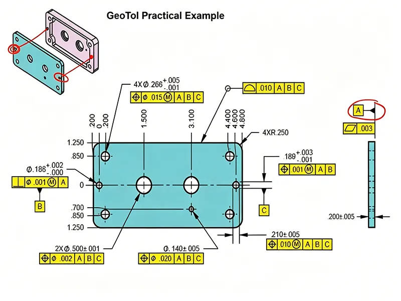
On a drawing, datum features are identified with datum symbols. KEYENCE explains that datum symbols use a white or black triangle, and the letters are oriented for the reader of the drawing. Other GD&T teaching material shows the same basic convention: a capital letter in a frame attached to the relevant feature, extension line, or size dimension. The practical result is that the datum letter marks the physical feature that will be used to establish the exact datum during setup or inspection.
The second place datums appear is inside the feature control frame. KEYENCE describes the feature control frame as the box that holds the geometric characteristic symbol, tolerance value, and datum references. When multiple datums are listed, they are written left to right in order of priority. NIST explains the same rule more formally: the first datum listed to the right of the tolerance value is primary, the next is secondary, and the next is tertiary. So while many drawings happen to assign letters alphabetically by importance, precedence is created by the order in the feature control frame, not by the alphabet alone. NIST also notes that the same datum can be primary in one datum system and secondary in another, depending on the control being applied.
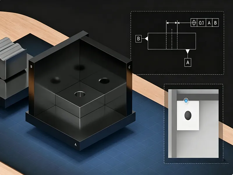
Once multiple datums are referenced together, they create a datum reference frame. This is the coordinate system the toleranced feature is evaluated from. KEYENCE describes a datum system as a group of datums combined to serve as a reference for toleranced features, and its example of a three-plane datum system shows the part being pushed against A, then B, then C until it is completely captured. ASME training materials likewise teach the datum reference frame as the connection between theory and the physical part, including the need to constrain six degrees of freedom and create a complete reference frame.
The classic beginner explanation is the 3-2-1 locating idea. Industrial training material and NIST publications describe the familiar practice of constraining the six degrees of freedom gradually: a primary relationship, then a secondary one, then a tertiary one, until the part can no longer translate or rotate in unwanted ways. It is easiest to visualize with three mutually perpendicular planes, but ASME teaching also shows that holes, slots, shafts, and widths can serve as datum features too, creating equivalent restraint through axes and center planes rather than flat faces alone.
How Datums Control Location, Orientation, and Geometric Tolerances
Datums matter because most geometric tolerances are not just about a feature by itself; they are about that feature relative to something else. Search documentation for industrial CMM software states that most geometric tolerances reference one or more datums, and that datums align the actual surfaces with the nominal geometry so that position, perpendicularity, runout, and related controls can be evaluated. NIST summarizes the same idea by saying datums are used extensively to locate and orient tolerance zones.
That is why a position tolerance usually references datums, why a perpendicularity tolerance often needs a datum plane or axis, and why a profile tolerance becomes far more powerful once it is tied to a meaningful reference frame. A positional requirement for a hole pattern, for example, is not just about where the holes happened to end up relative to the raw stock. It is about where those holes exist relative to the mounting plane, locating bore, center plane, or other functionally important feature that defines how the part is actually used. KEYENCE’s feature control frame explanation and industrial metrology references both make clear that the datum reference establishes what gets prioritized and in what order.
This is also where datums and dimensions work together rather than compete. The dimension tells you the theoretically exact distance, angle, or size that defines the ideal geometry. The geometric tolerance tells you how much real manufacturing variation is allowed around that ideal. The datums tell you the frame from which that ideal is measured. Without the datum reference frame, even a perfectly reasonable basic dimension can float in space and become open to interpretation. ASME teaching materials explicitly pair datum reference frames with basic dimensions, position tolerancing, and profile tolerancing for this reason.
A related misconception is that every part must always use three datums. In reality, the drawing uses as many datums as are needed for the specific control. Some form tolerances can be applied without any datum reference at all, while other functional requirements need one, two, or three datum references depending on how much orientation and location must be fixed. Teaching material on datum symbols states that a feature control frame should reference as many datum features as necessary to lock the required degrees of freedom, not more than necessary.
Where Datums Matter in Real Manufacturing
In CNC machining, datums translate drawing intent into setup logic. Renishaw explains that machine-tool probing supports automated workpiece setup, in-process control, and part verification, and that probing before, during, and after machining can reduce variation, rework, and scrap. That only works if the process knows what reference it is establishing. In practice, the selected datum scheme influences how a part is oriented in the vise or fixture, how offsets are set, what surfaces are probed first, and which features are trusted as the machining baseline. If the datum strategy is poor, precision machines only repeat a bad reference very consistently.
In inspection, datums are equally central, but there is an important nuance. A presentation from Mitutoyo America Corporation notes that measurements can never literally “conform” to ASME Y14.5 because the standard defines product requirements rather than measurement compliance methods, even though measurement methods are strongly influenced by the standard. ISO 5459:2024 makes a related distinction by saying the document defines the specification operator used to establish a datum or datum system, while the verification operator can take different physical or mathematical forms and is not the subject of the standard. That is why CMM programming, sampling strategy, fixturing, and algorithm choice still require engineering judgment even when the datum references on the print are perfectly clear.
The impact is not theoretical. In the Mitutoyo case-study material, using the intended datum rather than an alternate surface changed the datum-related uncertainty dramatically, even though both approaches were still judged acceptable against business needs. Industrial CMM documentation likewise says that each GD&T check is aligned relative to the specified datums, not necessarily whatever generic machine alignment happens to be convenient. Put plainly, datums are how inspection decides what “square,” “centered,” or “in position” actually means for that specific part.
In assembly and fixturing, datums are what make repeated location practical rather than accidental. Selection guidance from manufacturing sources emphasizes functionally important and mating features because those are the ones that determine how components contact each other in real use. That is also why overconstraint matters. One industrial example discussing slots for precision location shows the logic clearly: a pin in a hole can remove two translational degrees of freedom, while a pin in a slot removes the remaining rotational freedom without forcing the part into an impossible or stressed condition. The same datum thinking scales from small machined brackets to large irregular parts, where datum targets are often used because an entire rough or flexible surface is not the true assembly contact condition.
How to Choose Datums Well and Avoid Common Errors
The strongest datum selection starts with function. Manufacturing guidance recommends choosing datums in order of real importance: mating surfaces, functional part surfaces, easily identified features, and features with enough area or definition to support repeatable inspection. Tec-Ease emphasizes sufficient size and stable setup, while Andrews-Cooper recommends choosing the largest surface area that is significant to the assembly for the base datum. Those are not cosmetic preferences. They are ways to anchor the drawing to how the part actually works in the product.
A good datum scheme also has to survive all three worlds at once: design, manufacturing, and inspection. A datum that looks elegant on a CAD screen but is awkward to fixture, too small to repeatably touch, or unrelated to the assembly interface will create friction downstream. Renishaw’s work on automated setup and Mitutoyo’s measurement planning materials both show that accuracy and repeatability are process outcomes, not just drawing outcomes. The best datum is therefore not merely theoretically defensible; it is also stable to manufacture from and stable to measure from.
Most datum mistakes come from a few recurring misunderstandings. The first is mixing up the datum with the datum feature, as if the imperfect workpiece surface itself were already exact. The second is choosing an unstable or narrow surface as primary simply because it is easy to label. The third is overlooking how symbol placement changes meaning: a symbol on a cylindrical size feature creates an axis datum, while a symbol on a width feature can create a center plane rather than referring to one wall. The fourth is over-constraining the part with unnecessary references when the function does not require them. NIST, KEYENCE, and other GD&T references all separate these ideas carefully because real-world confusion here directly causes bad setups and bad inspections.
The last major error is ignoring the governing standard system. Mitutoyo’s GD&T training notes that ASME and ISO can differ significantly in defaults and interpretation, even when drawings look similar. So a well-written drawing should make its standard context clear, and a reviewer should confirm whether the part is being interpreted under ASME or ISO rules before arguing about datum behavior. This is especially important in multinational supply chains, mixed CAD/CMM environments, or contract manufacturing situations where assumptions travel farther than the drawing author intended.

Summary and FAQ
Datums are not just labels on a print. They are the reference system that connects design intent to machining setup, measurement alignment, and assembly fit. A datum is a theoretically exact reference; a datum feature is the real surface or feature of size from which that exact reference is established. The most common practical datum forms are plane datums, axis datums, center plane datums, and point datums. Together, they let engineers control where a feature should be, how it should face, and how inspection should evaluate it.
If there is one practical rule worth carrying into every drawing review, it is this: choose datums that match how the part functions, how it will be held, and how it will be measured. When those three viewpoints line up, tolerance schemes become clearer, setups become more repeatable, and inspection arguments become shorter. When they do not, even a technically “legal” datum scheme can become expensive.
FAQ
What are datums in engineering drawings?
Datums in engineering drawings are the exact reference planes, axes, lines, or points used to define where tolerance zones and measurements are established. Practically, they create the coordinate system that lets other features be located and oriented unambiguously. Standards and metrology references describe them as reference geometry derived from real part features and used to control location and orientation in technical documentation.
What is the difference between a datum and a datum feature?
A datum feature is the real feature on the part, such as a surface, hole, slot, shaft, or width. A datum is the theoretically exact geometry derived from that real feature. In practice, inspectors or fixtures use a simulated datum feature such as a surface plate, gauge, or mandrel to establish the datum. If a bore is designated as a datum feature, the datum is typically the exact axis derived from that bore, not the imperfect cylindrical surface itself.
Why are datums important in manufacturing?
They are important because manufacturing needs one repeatable reference language from drawing through setup, machining, inspection, and assembly. ASME describes GD&T as a common language for product realization, and machine-tool probing guidance shows that setup and verification depend on consistent references to control variation, reduce scrap, and improve process control. Without good datums, different teams may produce valid-looking but incompatible interpretations of the same print.
What are the main types of datums?
The main practical types are plane datums, axis datums, center plane datums, and point datums. A plane datum usually comes from a flat surface such as a mounting base. An axis datum comes from a cylindrical bore or shaft. A center plane datum comes from two opposed parallel surfaces such as a width feature or slot. A point datum can come from a spherical feature or similar precise locating condition.
How do datums work in inspection?
In inspection, datums establish the alignment from which geometric tolerances are evaluated. Industrial CMM documentation states that datum alignment is performed relative to the specified datums for each check, and that datums align actual measured surfaces with nominal geometry so that position, perpendicularity, runout, and related tolerances can be assessed. At the same time, both ISO and ASME-related measurement guidance make clear that the standard does not fully prescribe the measurement method itself, so inspection still requires planning, fixturing, and algorithm choices.
How do you choose the right datum?
Start with function. Choose features that matter most to assembly and operation, then prefer features that are stable, sufficiently large, clearly identifiable, and easy to measure repeatably. Large mounting faces, locating bores, and meaningful center planes usually make better datums than small cosmetic edges or inconsistent raw surfaces. The best scheme is one that keeps design intent, machining setup, and inspection alignment all pointing to the same physical reality.

