
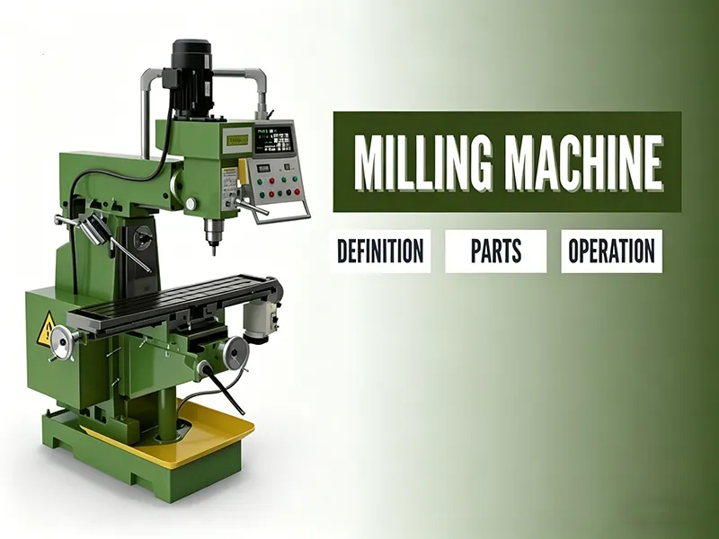
A milling machine is a versatile machine tool that uses one or more rotating cutting tools to remove material from a workpiece. In a typical setup, the workpiece is clamped to a table that can move in three axes (X, Y, Z) while the spindle-mounted cutter spins at high speed. By advancing the workpiece or the cutter along precise paths, a milling machine can cut flat surfaces, slots, holes, gears, and complex 3D contours. Unlike a lathe (where the workpiece rotates against a stationary single-point tool), a mill holds the workpiece stationary and presents it to a multi-point rotating tool. This fundamental difference means mills are ideal for making flat, angular, and irregular surfaces that would be difficult on a lathe. Milling machines are found in nearly every machining and manufacturing shop today, from small repair shops to high-tech aerospace plants. They are capable of shaping metal, plastic, and other solids with very high precision, which makes them a cornerstone of modern CNC machining services.
Modern milling machines range from simple manual knee mills to advanced CNC (computer numerical control) machining centers. All share the same basic principle: a rotating cutter progressively removes small chips from the workpiece as the table or cutter moves. By adjusting spindle speed, feed rate, and depth of cut, the operator can control how much material is removed on each pass and the quality of the surface finish. For example, a higher spindle RPM and slower feed produce a finer finish on steel, while cutting deeper per pass or using a larger cutter can speed up roughing operations. In CNC mills, these parameters are defined by a program, whereas in manual mills the operator sets them by hand.
Key points: Milling machines use rotating tools to remove chips from a fixed workpiece. They can machine flat surfaces, slots, holes, and 3D shapes. The workpiece is secured to a movable table while the cutter spins. The process requires controlling spindle RPM, feed rate, and depth of cut.
How a Milling Machine Works
In operation, the workpiece is first clamped securely to the mill’s table or vice. The cutting tool (milling cutter) is mounted in the spindle, which drives it to rotate. As the spindle spins, the table and/or the cutter are moved in one or more axes so that the cutter progressively engages the workpiece. Each cutting tooth on the tool shaves off small chips of material. Over many passes, this produces the desired shape or feature. Modern CNC mills automate this process: a programmed sequence tells the machine exactly how fast to move the table (feed), how fast to spin the cutter (spindle RPM), and how deep to cut on each pass. For example, face milling (making a flat surface) is done by moving the table under a wide face mill; slotting is done by feeding the cutter into the work to cut grooves.
Important parameters in milling include feed rate (how fast the table moves), spindle speed (the cutter rotation rate), and depth of cut (how thick each chip is). Selecting these depends on the material and tool. Using too high a feed or RPM can overheat and break tools, while too low values can leave burrs or waste time. In practice, machinists often refer to tooling charts or perform test cuts to dial in the optimal speeds and feeds for the material and cutter being used. During cutting, coolant or air blast is often used to remove heat and chips from the cutting zone. In summary, the spindle-driven cutter rotates and cuts away material while the table moves, and by coordinating these motions the mill “machines” the part.
Main Parts of a Milling Machine
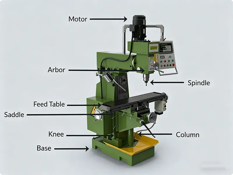
A milling machine is composed of several rigid structures and movable components. The major parts are:
- Base and Column: The base is the heavy foundation that supports the entire machine. It must be rigid to absorb cutting forces without deflecting. Sitting on the base is the column, a vertical structure that supports the spindle and transmission components. In many mills the column houses the drives and provides vertical support for the headstock or turret.
- Knee and Saddle: In a typical knee-type mill, a knee casting slides vertically on the column face. The knee carries the saddle, which slides horizontally in one direction. Together, the knee and saddle allow the table to be adjusted up/down and in/out for positioning. (Some mills do not have a movable knee; in “bed” mills the table is fixed, see below.)
- Table: The worktable is the flat T-slotted surface on which the workpiece (or fixtures) is clamped. It usually can move longitudinally (left/right) and sometimes crosswise (in/out) and vertically (up/down) via the knee. The T-slots hold clamps, vises, and fixtures for securing parts. The precision and flatness of the table surface directly affect machining accuracy.
- Spindle: The spindle is the rotating shaft that holds the cutter. It is driven by a motor through gears or belts. The spindle’s orientation (vertical or horizontal) and speed range determine the mill’s capabilities. Heavy-duty spindles deliver higher torque and rigidity for harder materials. The cutter is mounted in the spindle via collets or an arbor (an extension shaft).
- Milling Cutter: This is the actual cutting tool (end mill, face mill, etc.) that removes material. Different cutters are used for different operations (see below). The cutter must be mounted and secured in the spindle or arbor.
- Control/Drive System: Manual mills use handwheels and clutches to move the table and set speeds. Many modern mills are CNC controlled, with a computer interface that drives stepper or servo motors on each axis. CNC systems automate moves and allow precise repeatability, while manual mills give the operator direct control of the feeds.
- Additional Supports: Some mills have an overarm or turret for heavy cutters (common on horizontal mills), and some have drives for auto table feeds. Hydraulic or power features (like power feeds on the knee) may be included on advanced machines.
Key components: The base/column give rigidity, the spindle and milling cutters do the cutting, and the table (knee/saddle) supports and moves the workpiece. CNC controls have replaced many handwheels on modern mills.
Types of Milling Machines
Milling machines come in several configurations suited to different tasks:
- Vertical Milling Machine: The spindle is oriented vertically down towards the table. Vertical mills are very common in shops and are often used for general-purpose tasks like surfacing, slotting, and drilling. The spindle may have a fixed head or a swiveling turret. Small vertical mills (sometimes called knee mills) offer great flexibility for varied work, from making flat surfaces to pockets or drilling holes. They are generally easier to set up for multi-axis work.
- Horizontal Milling Machine: Here the spindle is horizontal. The cutter (often held on an arbor) extends from the spindle at right angles to the column. Horizontal mills excel at heavy cutting and producing deep slots or grooves, because the arbor can support multiple cutters and the machine is very rigid. They often have a geared head for high torque. A horizontal setup can remove large volumes of material quickly, making it suitable for rough machining larger or heavier parts.
- Universal Milling Machine: This is a type of vertical mill with additional articulation. A turret (universal) mill has a table that can swivel and a head that can tilt. This allows cutting at angles without repositioning the workpiece. Universal mills are used for complex parts where multiple surface orientations are needed in one setup. The turret milling machine (a kind of universal mill) fixes the spindle to the column and moves the table, providing great versatility.
- CNC Milling Machine: Any of the above machines may be CNC-equipped. CNC mills use computer control to move the table and spindle precisely along programmed paths. This allows very complex shapes, 3D contours, and high repeatability. 3-axis CNC mills are common, and more advanced 4- or 5-axis CNC mills can tilt or rotate the part for even more complex machining. CNC machining centers (vertical or horizontal) dominate modern production in aerospace, automotive, electronics, and medical industries.
- Bed-Type Milling Machine: A bed mill has a fixed table (bed) and the head moves up and down on the column (rather than the knee moving). This design is extremely rigid and is used for large, heavy work where stability under high cutting forces is needed. Bed mills can handle very large plates or castings (e.g. in mold making or large fixture machining). Because the table is fixed to the base, bed mills produce less vibration and can achieve high precision on large parts.
- Gantry Milling Machine: A gantry mill (also called a bridge mill) features a large bridge-like frame spanning the worktable. The spindle and its support move along this bridge (gantry), allowing machining of very large and heavy parts that wouldn’t fit on conventional mills. Gantry mills are common in aerospace and shipbuilding, where pieces like aircraft frames or hull sections are machined. Their rigid double-column structure supports machining on large sheets or blocks with minimal deflection.
- Turret Milling Machine: A turret mill is a subtype of vertical mill where the spindle is fixed but can be moved up/down by moving the table (or vise) up/down. The head (turret) can also swivel and tilt. Turret mills are popular as workshop machines because they allow quick tool changes and flexible work holding. They combine some benefits of bench-top mills with the strength of a floor model, making them well-suited for prototyping and intricate work.
Each type has its strengths. For example, vertical mills (including turret and CNC machining centers) are extremely common for varied work and finishing, horizontal mills shine in heavy material removal, while bed and gantry mills take on the largest jobs. Choosing among these depends on the size of parts, required rigidity, and precision needed.
Common Milling Operations
Milling machines can perform a wide range of cutting operations. Some of the most common include:
- Face Milling: Cutting flat surfaces (faces) on the workpiece. A face mill (with cutting teeth on the end and sides) removes material across the top of the part, leaving a smooth planar surface. This is used to flatten a surface or create a new reference face.
- Peripheral (Plain) Milling: Also called plain milling, it uses the cutter’s side teeth. The milling cutter’s axis is parallel to the surface being cut. This is suited for cutting slots, grooves, or flat surfaces parallel to the tool axis.
- Slot Milling: Cutting slots, keyways, or channels in the part. A straight-slot cutter or end mill is fed into the material to create a uniform groove. Common examples include T-slots on machine tables (using T-slot cutters) and keyways in shafts.
- End Milling: Using an end mill (cutter with teeth on the end and sides) to profile or pocket a workpiece. End mills can plunge directly into the material or cut along a contour. This is widely used for cavities, complex contours, and angled surfaces.
- Drilling and Boring: Although typically done on a drill press, milling machines can perform drilling, reaming, and boring by feeding a twist drill or boring head into the workpiece along the Z-axis. This adds flexibility so that holes can be machined without moving the piece to another machine.
- Thread Milling: Cutting internal or external threads with a rotating thread mill cutter. By plunging and helical milling, precise threads can be made on a mill, allowing different pitches and avoiding the need for taps/drills for different thread sizes.
- Profile/Contour Milling: Creating curved or complex 3D shapes. CNC mills commonly do this by following a programmed contour; a ball-nose cutter is often used for smooth curves on molds and dies.
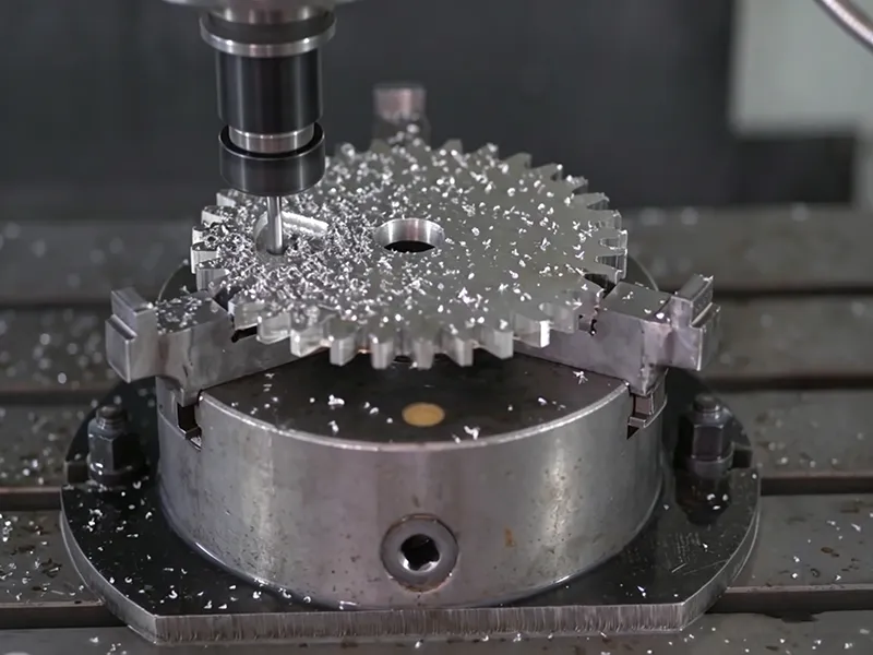
- Gear Cutting (Form Milling): Special cutters can machine gear teeth or splines by indexing the cutter and work in a coordinated fashion.
- Die/Mold Machining: CNC milling can carve out complex cavities and profiles needed for dies and molds in plastic injection or metal casting.
In summary, milling encompasses operations for flat surfaces (face milling), straight and shaped slots (peripheral/slot milling), holes and threads (drilling/boring/thread milling), and full 3D contours (profile milling). Different cutter types (see next section) are used for each.
Milling Cutters and Tools
The choice of milling cutter is crucial for each operation. Common cutter types include:
- End Mills: The most ubiquitous milling cutter. End mills have cutting teeth on the end face and sides. They come in flat-bottom, ball-nose, or corner-rounding styles. End mills are used for pockets, contours, profiles, and drilling (plunge cuts).
- Face Mills: Large-diameter cutters with multiple indexable cutting inserts on the face and periphery. They are used for high-volume removal of flat surfaces (face milling) and give a fine finish over wide areas.
- Ball Nose Cutters: End mills with a rounded tip (hemispherical end). Ideal for milling complex 3D surfaces, fillets, and molds, as they leave smooth contour lines on curved features.
- Slab Mills: Robust cutters used on horizontal mills for bulk material removal on large surfaces or for cutting slots. They can have many teeth and often use an arbor for support.
- T-Slot Cutters: Special end mills shaped like a “T” to cut the bottom width of a T-slot (e.g., machine table T-slots).
- Thread Mills: Thread-forming cutters used to cut screw threads. They can mill internal or external threads by helical interpolation.
- Woodruff Keyseat Cutters: For cutting keyways in shafts; shaped like a circular disk.
Cutters are typically made from high-speed steel (HSS) for general work or carbide for harder materials and higher speeds. Many modern mills use indexable insert cutters, especially for face and slab milling, where the cutting edges can be replaced when worn.
Materials Commonly Machined
Milling machines process a broad range of materials. Common examples:
- Aluminum: Soft and easy to machine. Aluminum’s low hardness and high thermal conductivity allow high spindle speeds and feeds. It’s used for aerospace parts, automotive components, electronic enclosures and prototypes. Burrs can form, so sharp cutters and chip control are important.
- Steel (Carbon Steel): Much harder than aluminum. Requires slower speeds and more rigidity. Carbon steel is ubiquitous (machinery parts, shafts, dies). A stiff machine and strong cutter are needed. Coolant is often used to prolong tool life.
- Stainless Steel: Hard, tough, and heat-resistant. Causes rapid tool wear and heat buildup. Requires very rigid setup, lower speeds, and specific tooling (often coated carbide or ceramic). Common in medical, food, and chemical equipment parts.
- Brass and Copper: Soft, ductile, very conductive. Easy to cut but can stick to tools. Often used for fittings, electrical parts, and decorative trims. Standard HSS end mills work well, but care is taken to avoid built-up edge.
- Titanium and Alloys: Very high strength-to-weight and corrosion resistance. Difficult to cut due to low thermal conductivity (so heat stays in tool) and springiness (chatter). Special carbide tools, slow feeds, and heavy coolant/cutting oil are needed.
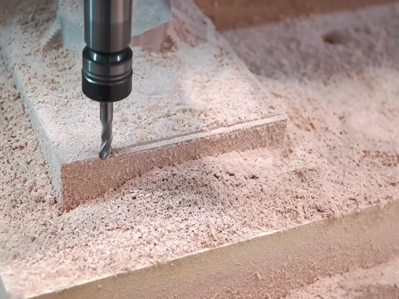
- Plastics: Much softer and melt easily. Very high spindle speeds and light cuts are used. Plastics can deform or melt if overheated, so high feed and chip load (to carry heat out) are used. Often machined on routing modes or special machines.
- Composites (e.g. carbon fiber): Require sharp tooling (often polycrystalline diamond) and high speed to avoid delamination.
In general, aluminum and plastics are easiest to mill, whereas steel, stainless, and titanium require more rigid machines and conservative cutting parameters. The choice of material influences the mill selection: heavy-duty mills for hard metals, high-speed mills for soft materials.
Applications of Milling Machines
Milling machines are used in nearly every manufacturing sector due to their versatility. Typical applications include:
- Precision Part Manufacturing: Milling can create precise flat faces, angles, and holes on engine parts, hydraulic components, and fixtures. Complex parts like brackets, housings, and machine elements are commonly milled to tight tolerances.
- Mold and Die Making: Milling carves out the cavities and contours in metal used for molds (plastic injection molds) and dies (metal stamping dies). The complex 3D shapes of molds often require CNC milling of hardened steel or aluminum.
- Automotive Components: Engine blocks, cylinder heads, transmission cases, suspension parts, and custom brackets are milled. The ability to handle both flat surfaces and pockets makes mills ideal for transmission gears and structural parts.
- Aerospace Parts: Milling’s strength-to-weight makes it key in aerospace. Turbine blades, airframe brackets, landing gear components, and aircraft structural parts are milled from aluminum, titanium, and nickel alloys.
- Medical Devices: Orthopedic implants, surgical instruments, and precise medical components are milled from stainless steel, titanium, and plastics. The high precision of CNC milling is critical for biocompatible parts.
- Electronics and Enclosures: Heatsinks, cases, connectors, and circuit board holders often start as milled aluminum or plastic parts. Mills produce the holes, slots, and pockets needed for PCBs and assemblies.
- Custom Prototypes: Rapid prototyping often uses milling to quickly shape concept parts. Even 3D-printed parts may be refined by milling key surfaces.
- General Fabrication: In job shops and maintenance, mills are used for producing shafts, gears, keyways, flat plate work, and for repairing worn parts.
In essence, anywhere flat surfaces, slots, holes, or complex shapes are needed in a solid block, milling is the go-to process. As one summary notes, mills are vital for producing “gears, slots, keyways, dies, and molds” across many industries. Their ability to handle everything from tiny precision parts to large machine frames makes them indispensable.
Milling Machine vs. Lathe Machine
While both mills and lathes remove material, they do so in opposite ways. On a lathe, the workpiece rotates around a horizontal axis against a stationary single-point tool. Lathes excel at making round or cylindrical parts (shafts, bushings, threads on a cylinder). In contrast, on a milling machine, the cutting tool rotates and the workpiece remains fixed or is fed linearly. The mill uses multi-point cutters (often with several teeth) to grind away material across a surface. In short, a lathe spins the part under a tool, whereas a mill spins the tool over a fixed part. This means a mill can produce flat surfaces, slots, and irregular 3D shapes, while a lathe is best for round and symmetrical parts.
Most modern machine shops have both mills and lathes, as they complement each other: for example, a shaft might be turned on a lathe and then milled to add flats or holes. When deciding which to use, consider the geometry: if the critical features are cylindrical (holes, shafts), use a lathe; if flat surfaces, slots, or complex profiles are needed, use a mill.
Manual Milling Machine vs. CNC Milling Machine
Manual milling machines require the operator to control each axis with hand wheels or levers. They are simple to set up for one-off jobs and cost less to purchase. Skilled operators can perform a wide range of work by manually positioning the table and engaging feeds. Manual mills are well-suited for maintenance, repairs, small batches, or where programming is not justified. However, accuracy and repeatability depend on operator skill, and complex shapes require careful incremental cutting.
In contrast, CNC milling machines use computer numerical control. A CAD drawing of the part is converted into a program (G-code) that tells the machine exactly how to move the table and spindle. CNC offers several advantages: it can achieve extremely consistent precision, perform multi-axis complex moves, and run unattended for batch production. CNC machines can automatically change tools and repeat the same operations on many parts, which greatly increases efficiency. As one source explains, CNC mills provide “increased accuracy, repeatability, and efficiency… producing intricate parts with minimal human intervention”. On the downside, CNC machines are more expensive and require upfront programming time.
Which to choose? For simple parts or low-volume prototyping, a manual mill is often sufficient and cost-effective. For high-precision parts, complex geometry, or high-volume runs, CNC milling is usually preferred. Many shops use a combination: manual mills for flexible, one-off tasks, and CNC mills for production and intricate components.
Advantages of Milling Machines
Milling machines offer several key benefits in manufacturing:
- High Precision and Accuracy: CNC-controlled mills can position the cutter to within thousandths of an inch, yielding tight tolerances and excellent repeatability. Even manual mills with precise readouts can achieve very accurate features.
- Versatility: A single milling machine can perform a wide variety of operations (milling, drilling, boring, tapping). It can handle many materials (metals, plastics, composites) and produce flat, curved, or irregular surfaces.
- Complex Geometry: Modern multi-axis CNC mills can cut highly complex 3D contours and angled surfaces that would be impractical or impossible on simpler machines.
- Efficiency and Speed: Automated tool changes and high spindle speeds allow mills to remove material quickly. They reduce waste by precisely cutting only what’s needed.
- Material Removal Rate: For large surface work, heavy cutting, and batch production, mills (especially horizontal or gang-milling setups) can remove large volumes of material effectively.
- Repeatability: Once a CNC program is created, a mill can make hundreds or thousands of identical parts consistently. This is essential in industries like aerospace and automotive.
- Wide Material Range: From soft plastics to very hard alloys, there is a milling cutter and machine setup for almost every material.
In sum, milling machines are valued for their precision, flexibility, and high productivity.
Limitations of Milling Machines
Despite their strengths, milling machines have some limitations:
- Cost: High-quality mills, especially CNC and large-scale machines (gantry, multi-axis), can be expensive to buy and maintain. The tooling and fixturing costs also add up.
- Setup Complexity: Complex parts often require careful fixturing and multiple setups, which can be time-consuming. Achieving perfect alignment for multi-face parts takes skill or special fixtures.
- Programming Time: For CNC mills, creating the CNC program (CAM work) for a new part can take significant time. For small runs, this overhead may not be justified.
- Skill Requirement: Manual milling depends heavily on operator expertise. Even CNC milling requires knowledgeable operators/programmers to optimize tool paths and parameters.
- Size Limitations: A given mill has a fixed table/work envelope. Very large parts may require splitting into segments or using specialized large machines (bed, gantry).
- Geometry Constraints: Certain features are better done on other machines. For example, very deep holes or internal contours might be drilled or done by other processes. Extremely long, slender shafts are better on lathes.
- Tool Wear and Heat: Hard or abrasive materials (stainless, composites) can wear cutters quickly. Controlling heat is critical. Poor cooling or chip evacuation can compromise quality.
In other words, mills are not one-size-fits-all. Strength often trades off with cost and complexity. In design, engineers must balance strength vs. practicality: the strongest material or tightest tolerance is only worth it if the part can be reliably machined.
Choosing the Right Milling Machine
Selecting a milling machine requires matching its capabilities to the job’s requirements:
- Part Size: Small parts can be made on bench-top or vertical mills. Large parts (plates, big castings) may need a bed-type or gantry mill with a large work envelope.
- Material: Hard or heavy materials (hardened steel, titanium) need a rigid machine with high spindle power and torque. Softer materials (aluminum, plastics) allow higher speeds; even desktop CNC mills can handle them.
- Accuracy/Tolerance: High-precision parts favor CNC machines with finer resolution and thermal compensation. Tight flatness or finish demands a stable, well-calibrated machine.
- Production Volume: For one-offs or small batches, a manual mill or simple CNC may suffice. For large volumes, automated CNC with tool magazines and possibly multiple pallets is better.
- Complexity: Simple prismatic parts might be done on a 3-axis mill. Parts with undercuts, curves, or multiple faces may need multi-axis CNC or a universal turret.
- Budget: Cost of machine, tooling, and fixturing must fit the project budget. Sometimes it’s worth using a lower-spec machine for a cost benefit if tolerances allow.
- Space: Floor space and shop layout may favor vertical mills. Very large gantry mills are typically found in specialized factories.
In practice, shops often keep a range of mills. A small vertical knee mill handles daily chores and fixes, while a big 5-axis CNC covers complex work. To choose for a new application, list the critical factors—workpiece size, material hardness, precision, and quantity—or send your drawing for a quote before production.
Safety Tips for Milling Machines
Working with milling machines involves spinning parts and sharp tools, so safety is paramount. Key safety rules include:
- Secure the Workpiece: Always clamp or fixture the workpiece firmly before cutting. A loose part can spin like a “merry-go-round” and cause serious injury.
- No Loose Items: Remove jewelry and loose clothing, and tie back long hair. Loose sleeves or gloves can get caught in a spinning cutter. In fact, it is strongly advised to remove gloves when operating a mill.
- Wear PPE: Always wear safety glasses or a full-face shield to protect against flying chips. Hearing protection is also recommended in a busy shop.
- Machine Guards and Keys: Ensure guards and shields are in place. Remove any chuck keys or wrenches from the machine before turning it on.
- Stop Before Adjusting: Never reach over or near a rotating cutter. Always stop the spindle before measuring, cleaning, or changing tools. Use a brush or vacuum to remove chips – never use your bare hands.
- Check Setup: Before starting, double-check that the cutter will not hit clamps or the vise. Be aware of the cutting direction and have an emergency stop within reach.
- Use Correct Speed/Feed: Avoid excessive cutting forces by using recommended feeds and speeds. Overloading the cutter can cause breakage and accidents.
- Keep the Area Clean: Coolant spills or metal chips on the floor can be slip hazards. Clean up promptly.
- Training: Only trained personnel should operate mills. Understand how to use the controls, and never try risky maneuvers. If abnormal sounds or vibrations occur, stop immediately and inspect.
By following these precautions – such as clamping work securely, using eye protection, and never cleaning the cutter while it’s rotating – the risk of accidents is greatly reduced.
Common Mistakes When Milling
Even experienced machinists can make errors that affect quality or safety. Common milling mistakes include:
- Improper Clamping: Failing to clamp the workpiece tightly can allow it to shift or lift during cutting. Always check that the part is secure in the vise or fixture before milling.
- Wrong Tool Selection: Using an inappropriate cutter for the material or operation can ruin the cut. For example, using a high-speed steel tool on a hardened steel block will quickly dull the tool. Always choose the right cutter material (HSS, carbide, etc.) and geometry for the job.
- Dull or Damaged Tools: Cutting with worn tools leads to poor finish, overheating, and tool breakage. Inspect cutters for wear and re-sharpen or replace them before they become a problem.
- Incorrect Speeds and Feeds: Running the spindle too fast or too slow, or feeding at the wrong rate, can cause chatter, poor finish, or tool failure. Use manufacturer charts or software to calculate the optimal spindle speed and feed rate for your material and tool.
- Poor Chip Control: Letting chips accumulate can scratch the part, clog the cutter, and cause heat buildup. Use coolant and ensure chips are cleared away. Consider cutters with chip breakers or using air blasts.
- Skipping Setup Steps: Rushing the setup often results in errors. Common issues are misaligned tools, incorrect zero points, or incomplete calibration. Always double-check alignments and settings before cutting.
- Ignoring Coolant/Lubrication: Some machinists underutilize coolant, leading to excess heat and tool wear. For metals like steel and titanium, proper coolant flow is essential. Conversely, flooding certain plastics with coolant can cause them to swell, so use coolant judiciously based on material.
- Sequence Errors: Not planning the operation sequence can cause mistakes. For example, cutting a final keyway too early may distort a loosely clamped part. Plan roughing cuts first, then finishing passes.
- Human Error: Distractions or fatigue can lead to mishandling the feed controls or misreading a measurement. Stay focused and take breaks if needed.
By being aware of these pitfalls and addressing them – for example, choosing the correct tool and speeds – you can improve efficiency and part quality. Training and checklists can help avoid setup and procedural mistakes.
Milling Machines in Modern Manufacturing
Milling machines remain a driving force in modern manufacturing, especially with the advent of CNC technology and advanced toolpaths. Key trends include:
- CNC and Automation: CNC milling centers are integrated with CAD/CAM software, allowing designers to create complex 3D geometries in software and then precisely machine them. Multi-axis CNC mills (4-axis, 5-axis) can mill undercuts and compound angles in one setup. Automatic tool changers and pallet changers speed up production.
- Digital Control and Monitoring: Many mills now feature real-time monitoring (sensors on spindles and tool holders) to detect tool wear or breakage. This increases uptime and consistency. Digital readouts and DROs even on manual mills have greatly improved accuracy over purely mechanical indicators.
- Material Innovation: New materials like carbon fiber composites or high-strength alloys require milling techniques tailored to each material’s properties. This drives innovation in tool coatings, cryogenic cooling, and vacuum chucks.
- High-Speed Machining: Ultra-high-speed spindles and light, sharp cutters allow mills to remove material at much higher rates for aluminum and plastics, reducing cycle time.
- Additive/Subtractive Hybrid: Some modern machines combine 3D printing (additive) heads with traditional milling on the same platform, enabling rapid prototyping and repair.
- Industry 4.0: Networked milling machines can be part of a digital factory. Job data, maintenance schedules, and tool inventories are managed centrally, improving efficiency and traceability.
Overall, advances in milling technology have increased precision, flexibility, and integration into fully automated production lines. However, the core principle remains: a rotating cutter shaving chips from a workpiece.
Summary
A milling machine is a fundamental manufacturing tool that removes material from a workpiece using one or more rotating cutters. It works by feeding the fixed part against the spinning cutter, with the table moving in X, Y, and Z axes to shape the part. Key components include the sturdy base and column, a moving table, and the spindle which holds the cutter.
There are many types of mills: vertical and horizontal configurations handle different workloads, turret/universal mills add angle capability, bed mills support large heavy parts, gantry mills handle gigantic workpieces, and CNC mills bring automation and multi-axis control.
Milling operations (face milling, slotting, drilling, etc.) use different cutters (end mills, face mills, ball-nose, etc.) to produce flat surfaces, slots, holes, threads, and complex profiles. Materials commonly milled include aluminum, steel, stainless steel, brass, titanium, and plastics, each requiring appropriate cutting strategies.
Milling machines are extremely versatile. They make everything from simple mounting holes to complex aerospace components. Their precision and flexibility make them essential in industries such as aerospace, automotive, medical, electronics, and mold-making. When selecting a mill, consider the size of your parts, material, required precision, and production volume. A small manual mill may suffice for prototypes, while a large CNC gantry mill may be needed for huge molds.
In use, safety and technique are critical. Always clamp parts securely, wear protection, and follow proper feeds and speeds. Avoid common mistakes like using worn tools or incorrect speeds. With the right setup and parameters, milling machines can produce high-quality parts efficiently.
Key takeaways: Milling machines cut with a rotating tool on a fixed workpiece. They come in various types (vertical, horizontal, CNC, gantry) to suit different tasks. Modern CNC mills achieve very high precision and handle complex shapes. Despite their cost, their accuracy and versatility make them indispensable in machining. By understanding how they work and observing best practices, operators can take full advantage of milling machines’ capabilities.
FAQ
What is a milling machine?
A milling machine is a machining tool that removes material from a workpiece using one or more rotating cutters. It secures the workpiece to a table and feeds it against the spinning cutter to produce flat surfaces, slots, holes, and complex shapes.
How does a milling machine work?
The cutter is mounted on a spindle and spins at high speed. The workpiece is clamped to a movable table. As the table (or cutter) moves in various axes, the cutter shaves off material bit by bit. Feed rate, spindle speed, and depth of cut are controlled to shape the part.
What are the main types of milling machines?
Key types include vertical mills (spindle vertical), horizontal mills (spindle horizontal), universal/turret mills (adjustable head), bed-type mills (fixed table), gantry mills (bridge structure for large parts), and CNC mills (computer-controlled).
What is a milling machine used for?
Milling machines are used for precision machining in manufacturing. They make flat faces, slots, grooves, holes, keyways, gears, and 3D contours in a wide range of materials. Industries include aerospace, automotive, medical, electronics, and general fabrication.
What is the difference between a milling machine and a lathe?
A lathe rotates the workpiece against a stationary tool, making cylindrical parts. A milling machine rotates the cutting tool against a stationary (or linearly fed) workpiece. Milling machines use multi-point cutters; lathes use single-point tools.
Is a CNC milling machine better than a manual one?
CNC mills offer automation, higher precision, and repeatability, ideal for complex or high-volume work. Manual mills are less expensive and more flexible for quick setups or simple jobs. The choice depends on part complexity, quantity, and budget.
What materials can be machined on a milling machine?
Almost any solid material can be milled. Common ones are aluminum, steel (including stainless steel), brass, titanium, plastics, and composites. The machine’s power and cutter type must match the material hardness and size. For example, steel requires more rigidity and slower cutting than aluminum.
What is the difference between vertical and horizontal milling machines?
In a vertical mill, the spindle (cutter) points down. This is versatile for face milling and general work. In a horizontal mill, the spindle lies horizontally, often using an arbor for multiple cutters; this is stronger for deep cuts and large-volume material removal.
Why is CNC milling important?
CNC milling uses computerized control to move the table and spindle. It allows machining of very complex shapes with minimal human error, tight tolerances, and efficient multi-part production. Industries like aerospace, automotive, electronics and medical rely on CNC mills for their precision and speed.

