
A coordinate measuring machine, or CMM, measures the dimensional and geometric characteristics of manufactured parts by collecting three-dimensional point data from their surfaces. CMM programming converts engineering drawings, CAD models, GD&T requirements, and inspection plans into repeatable instructions that tell the machine how to align a part, move its probe, measure features, calculate deviations, evaluate tolerances, and generate inspection reports. Modern metrology software can create inspection plans from CAD or product manufacturing information and execute them automatically across repeated production parts.
This automation reduces dependence on manual feature location and improves consistency when inspecting complex or high-volume CNC parts. However, effective CNC quality control requires more than automated probe movement. Incorrect datum alignment, unsuitable probe selection, weak point distribution, unstable fixturing, thermal variation, or incorrect tolerance interpretation can produce misleading conclusions. NIST research identifies probing strategy, stylus configuration, algorithms, fixturing, temperature, and operating parameters as important contributors to CMM measurement uncertainty.
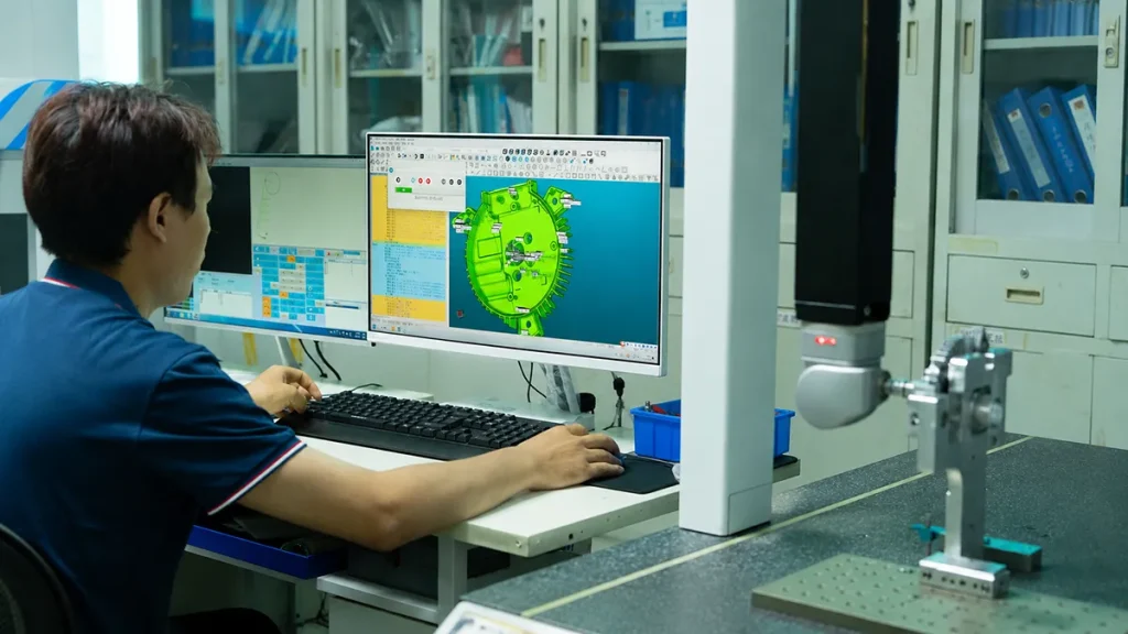
Need precision CNC parts with dimensional inspection reports? Send us your drawing, CAD model, tolerance requirements, required report format, and production quantity for a manufacturing and inspection review.
What Is CMM Programming?
CMM programming is the process of creating the instructions and measurement logic used by a coordinate measuring machine to inspect a physical part. The program defines where the probe moves, which points or scan paths it measures, how the software constructs geometric features, how the part is aligned to its design coordinate system, and how measured results are compared with drawing requirements.
A typical CMM program contains more than a list of dimensions. It may specify the probe and stylus configuration, qualification data, datum alignment, feature sequence, approach vectors, travel speeds, clearance movements, fitting algorithms, GD&T evaluations, output units, report fields, and pass-or-fail rules. Commercial CMM platforms support both direct machine programming and offline programming from CAD data.
Programs may be created by moving the probe manually to teach the machine, selecting nominal features from a CAD model, entering drawing values directly, or developing the complete routine on a separate offline workstation. Once validated, the same program can be reused for first-article inspection, in-process checks, final inspection, production sampling, and repeated batches of the same part revision.
| Term | Meaning |
|---|---|
| CMM measurement | Collecting dimensional point or scan data from a physical part |
| CMM programming | Creating the sequence, movement instructions, construction logic, and evaluation rules used to perform the measurement |
| Inspection plan | Defining which characteristics, datums, dimensions, and tolerances must be verified |
| Measurement report | Presenting nominal values, actual results, deviations, limits, and acceptance status |
These activities are connected but not interchangeable. An inspection plan defines what must be checked; the CMM program defines how the check will be executed; measurement collects the data; and the report communicates the results.
A CMM program does not improve the physical accuracy of a machined part. It determines how reliably the part’s existing geometry is evaluated. Even a highly accurate machine can return an unrepresentative result when the sampling strategy, alignment, fitting method, or probe setup does not match the inspection objective. NIST has shown that the number and angular distribution of points used to calculate a small circular feature can change measurement uncertainty dramatically.
How Does CMM Programming Work?
A reliable CMM routine follows a connected measurement logic: understand the design requirement, establish the part coordinate system, select a capable probing configuration, collect representative data, construct the required geometry, evaluate it under the applicable drawing standard, and document the result.
Import and verify the drawing or CAD model. Where available, the programmer imports the nominal three-dimensional CAD model and reviews the controlled two-dimensional engineering drawing. The drawing remains essential because it normally identifies dimensions, datum references, feature-control frames, material conditions, surface requirements, notes, revision status, and customer-specific inspection instructions. CAD-based software can select nominal features graphically, while systems that support product manufacturing information may automatically create portions of an inspection plan.
Before programming begins, the programmer should confirm:
- The correct part number, drawing revision, units, material, and CAD revision
- Critical-to-quality dimensions and assembly interfaces
- The applicable GD&T standard and drawing-specific notes
- Required inspection quantity, sampling frequency, and report format
- Whether the customer expects a full dimensional report, first-article format, capability data, or selected-characteristic report
Define the part coordinate system. The machine has its own coordinate system, but inspection results usually need to be reported in the coordinate system defined by the engineering drawing. The program therefore measures datum features and uses the specified datum reference frame to establish the origin and the X, Y, and Z directions.
For many prismatic components, a 3-2-1 concept can constrain the part’s six degrees of freedom: three contacts establish a primary plane, two establish secondary orientation, and one establishes the remaining origin direction. However, not every datum reference frame is a simple plane-line-point arrangement. Cylinders, datum targets, hole patterns, slots, freeform surfaces, maximum-material-boundary conditions, and partially constrained datum systems may require different alignment logic. ASME describes datums as theoretical references used to locate and orient features and emphasizes that datum simulation should reflect part function.
A useful distinction is that a rough or start alignment helps the CMM find the part safely, while the final measurement alignment should reproduce the drawing’s functional datum reference frame. A convenient machine setup must not silently replace the datum scheme specified by design.
Select the probe and stylus. The probing configuration should be chosen according to the feature size, depth, accessibility, surface condition, required uncertainty, and expected cycle time. Variables include probe type, stylus-ball diameter, shaft material, stylus length, extensions, star arrangements, disc styli, angled styli, and probe-head orientation.
The stylus ball must fit the feature while remaining large enough to avoid inappropriate contact with surface texture or small irregularities. The stylus should generally be as short and stiff as practical. NIST identifies stylus bending, probe repeatability, probe lobing, approach velocity, stylus configuration, and effective ball-diameter calibration as uncertainty contributors; its analysis notes that bending sensitivity increases strongly with stylus length. Renishaw likewise recommends reducing excessive stylus length and using shorter, stiffer configurations when troubleshooting measurement performance.
Deep bores and hidden features may require extensions or angled configurations, but each additional joint, extension, or orientation can affect rigidity, calibration requirements, accessibility, and collision risk. Motorized probe heads can automatically reorient sensors to reach features on different faces, but the necessary positions must be qualified and validated.
Program the measurement path. For every feature, the routine defines how the probe reaches the measurement area and how it leaves safely. The path can include approach points, pre-hit distances, retract distances, probing directions, clearance planes, transfer points, scanning vectors, travel speeds, scanning speeds, and probe changes.
Movement between features is not merely a cycle-time concern. Probe approach direction and velocity, machine acceleration, ram extension, probe orientation, and scanning dynamics may influence the resulting uncertainty. NIST identifies operating speed, approach direction, acceleration, and machine location as measurement-specific variables.
Clearance moves should account for the complete inspection environment, including clamps, fixture towers, neighboring parts, change racks, reference spheres, bosses, deep pockets, and unexpected loading variation. Offline software can model the machine, probe, fixture, and part so that the programmer can simulate paths before running them on physical equipment.
Measure, construct, and evaluate features. The CMM collects surface coordinates and uses mathematical fitting or construction logic to derive features such as points, lines, planes, circles, cylinders, cones, spheres, slots, widths, intersections, and symmetry or median planes. Coordinate-measurement software determines dimensional characteristics by analyzing the three-dimensional point data acquired from the part.
Constructed features may be based on direct measurements or relationships between previously measured features. Examples include:
- An intersection point created from two measured lines
- A bolt-circle diameter derived from several hole centers
- A center plane calculated between two opposing surfaces
- A width derived from parallel planes
- A cone axis used to evaluate orientation
- A pattern center used for a datum or positional evaluation
The selected fitting method also matters. Least-squares, minimum circumscribed, maximum inscribed, minimum-zone, and other algorithms do not necessarily answer the same functional question. For example, the best-fit diameter of a bore may not represent the largest pin that can pass through it. The fitting method should correspond to the drawing standard, software implementation, and functional inspection requirement.
Compare actual results with tolerances. Nominal values come from the drawing or CAD model. The software compares the calculated actual result with the specified upper and lower limits or geometric tolerance zone. It then calculates deviation and applies the inspection plan’s acceptance logic.
Results may be classified as:
- Pass: The characteristic is within its acceptance limits.
- Warning: The result remains within tolerance but has entered a defined process-warning band.
- Fail: The evaluated characteristic exceeds the applicable limit or tolerance zone.
The programmer must confirm the drawing standard and revision used for interpretation. The official ASME Y14.5 dimensioning and tolerancing standard establishes symbols, rules, definitions, datum relationships, modifiers, and tolerance-zone principles used to communicate GD&T requirements. ISO GPS drawings may apply different defaults or interpretation rules.
Generate the inspection report. A CMM report commonly includes the part number, drawing revision, serial or lot number, nominal values, measured values, upper and lower limits, deviations, GD&T results, acceptance status, inspection date, machine identification, operator, program revision, and probe information.
Reporting platforms can produce standard or customized templates and aggregate results for trend analysis or statistical process control. ZEISS PiWeb, for example, is designed to connect measurement results with reporting, quality-data management, statistical analysis, and shop-floor decisions, while CMM software such as CALYPSO supports customized measurement protocols and inspection-plan versioning.
CMM System Components and Programming Workflow
Successful automated inspection depends on the entire measurement system—not only the program file.
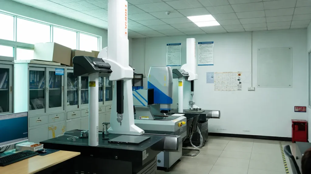
The coordinate measuring machine. Common CMM architectures include bridge, gantry, cantilever, and horizontal-arm machines, as well as portable measuring arms. Each configuration serves different part sizes, access requirements, accuracy classes, and production environments. A bridge CMM is widely used for precision prismatic components; gantry systems accommodate very large workpieces; horizontal-arm machines provide side access to large structures such as vehicle bodies; and portable arms emphasize mobility and flexible shop-floor measurement. CMM performance and acceptance testing are commonly addressed through standards in the ISO 10360 series.
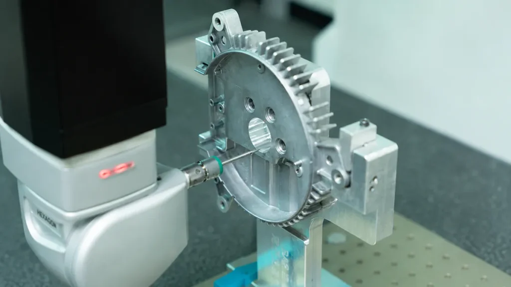
The probe system. A CMM may use a touch-trigger probe, analog scanning probe, optical sensor, laser scanner, vision system, or a multisensor configuration. Touch-trigger probes capture discrete surface points. Scanning probes maintain contact while collecting a continuous or high-density stream of surface data, making them especially useful for form, profile, and complex-surface evaluation. Renishaw states that scanning probes can collect hundreds of points per second, while touch-trigger probes gather individual points.
Scanning is not automatically superior for every characteristic. Discrete probing can be efficient for feature size and location when form variation is not a major part of the inspection objective. Scanning provides richer information when circularity, cylindricity, profile, or local shape variation is functionally important. Probe choice should therefore follow the measurand rather than a general preference for more data.
The stylus system. Common stylus arrangements include straight, star, disc, cylinder, angled, and extended configurations. A straight stylus offers simplicity and rigidity; star styli can access several surfaces without repeated head indexing; disc styli can contact features that are difficult to reach with a ball; cylinder styli may be appropriate for certain thin or sheet-like surfaces; and extended or angled assemblies reach recessed geometry.
Every configuration used in the program must be correctly defined and qualified. Multiple styli and indexed probe positions introduce offset relationships that must be known accurately. NIST testing found larger probe-performance values in certain multi-position configurations than in comparable single-position measurements, illustrating why reorientation and offset errors must be included in measurement planning.
CMM software. The software manages CAD import, probe definition and qualification, alignment, path generation, feature construction, GD&T evaluation, collision checking, reporting, data export, and—in some systems—statistical analysis or process integration. Current commercial software supports offline CAD programming, virtual machine environments, automatic plan creation from model-based definition, and inspection-plan version control.
Fixtures and workholding. Fixtures hold the part in a stable, repeatable position while preserving access to the required surfaces. The fixture should resist probe forces and machine acceleration without allowing the part to slip. At the same time, clamps must not deform thin walls, soft materials, molded components, sheet-metal parts, or slender features.
Over-constraining a part can be as damaging as insufficient support. NIST identifies clamping distortion, slippage, deformation under part weight, thermally induced distortion, and mounting that does not represent part function as potential sources of measurement error.
The measurement environment. Temperature is one of the most important environmental influences in dimensional metrology. The standard reference temperature for industrial dimensional measurement is 20°C, and dimensional results taken at other temperatures require appropriate correction and uncertainty consideration. A part taken directly from machining may have a nonuniform and changing internal temperature even when its surface appears stable.
Vibration, airborne contamination, shop-floor debris, airflow, machine foundation, air-bearing supply, humidity, and utility stability can also affect the machine or the measured component. A well-written program cannot compensate for an unstable part, loose fixture, contaminated stylus, damaged probe, or rapidly changing thermal environment.
Practical workflow from drawing review to production release
Step one—review the engineering requirements. Identify critical-to-quality dimensions, datum reference frames, GD&T callouts, fit conditions, assembly interfaces, profile requirements, special notes, and customer reporting expectations. Surface finish should be included in the inspection plan, but a conventional tactile CMM does not automatically replace a dedicated roughness instrument. Some multisensor CMM systems can accept specialized surface-finish probes, while other applications require separate equipment.
Step two—plan the inspection sequence. Decide which features establish the start and final alignments, which features must be inspected before any part rotation, where probe changes are required, and how the program will minimize nonmeasurement travel. The sequence should preserve datum integrity and avoid measuring flexible features after they have been disturbed.
Step three—qualify the probe. Probe qualification measures a calibrated reference sphere so the system can determine the effective stylus-ball size and its position relative to the machine. Every stylus and orientation used in the routine must have valid qualification data. Regular requalification supports measurement performance, particularly after changing a stylus, changing the configuration, experiencing a collision, or suspecting probe damage.
Step four—align the part. Measure the primary, secondary, and tertiary datum features—or another appropriate datum structure—and establish the drawing coordinate system. Confirm that the alignment constrains the intended degrees of freedom without introducing an unauthorized best fit.
Step five—measure the required features. These may include outside and inside diameters, hole positions, slots, planes, angles, profiles, wall thicknesses, edge distances, bolt patterns, and mating surfaces.
Step six—apply dimensions and GD&T. Connect each reported characteristic to the correct measured or constructed feature, datum reference frame, material-condition modifier, tolerance zone, and evaluation rule.
Step seven—simulate and check collisions. Review probe-to-part, probe-to-fixture, head-to-part, extension-to-wall, and change-rack risks. Confirm safe rapid moves, sufficient clearance, accessible probe directions, and valid sensor orientations. Offline simulation can reduce CMM downtime, but the digital environment must accurately represent the real machine, fixture, probe rack, and loaded part.
Step eight—run a validation part. Compare key automated results with calibrated gauges, known reference dimensions, manual inspection, a master part, or an approved previous method. Repeated runs and repositioning studies can help identify alignment instability, fixture sensitivity, and poor repeatability.
Step nine—release the controlled program. Record the approved program revision, drawing and CAD revisions, fixture identification, probe assembly, qualification requirements, report template, inspection frequency, and validation status. Production operators should not edit controlled geometry, tolerance, or alignment logic without formal review.
What Features and Tolerances Can a CMM Inspect?
A capable CMM can inspect a wide range of dimensional and geometric characteristics, provided that the feature is physically accessible, the sensor is suitable, the program represents the drawing requirement, and the measurement uncertainty is appropriate for the tolerance.
| Inspection category | Typical features or controls |
|---|---|
| Size and distance | Diameters, lengths, widths, heights, radii, angles, wall thicknesses, slot widths, hole spacing, and feature-to-feature distances |
| Form | Straightness, flatness, circularity, and cylindricity |
| Orientation | Parallelism, perpendicularity, and angularity |
| Location | Position, coaxial relationships, and feature patterns |
| Runout | Circular runout and total runout |
| Profile | Profile of a line, profile of a surface, contours, and freeform geometry compared with nominal CAD data |
Engineering drawings use GD&T symbols and controls to define requirements such as form, orientation, position, profile, and runout relative to applicable datum reference frames. The exact CMM evaluation must follow the governing standard and revision identified by the drawing.
Dimensional features. CMM software can calculate length, width, height, diameter, radius, angle, hole spacing, slot size, wall thickness, and distances between surfaces, axes, centers, or constructed elements. The result depends on how the underlying geometry is defined. A “diameter” based on a least-squares circle may differ from a two-point diameter or a functional maximum-inscribed diameter.
Form tolerances. Straightness, flatness, circularity, and cylindricity evaluate the shape of an individual feature without necessarily locating it to another datum. These controls often require more extensive sampling than a basic size check because local highs, lows, lobing, taper, or waviness may be missed by a few isolated points.
Orientation tolerances. Parallelism, perpendicularity, and angularity evaluate a feature’s orientation relative to one or more datum references. Accurate evaluation therefore depends on both the measured feature and the datum feature simulation used to establish the reference frame.
Location tolerances. Position evaluates the location of a feature or pattern relative to basic dimensions and applicable datums. The program must correctly implement feature size, tolerance modifiers, datum precedence, datum mobility, projected zones, composite controls, and pattern relationships where specified.
Legacy drawings or some ISO-based specifications may call for concentricity or symmetry. Under ASME Y14.5-2018, the concentricity and symmetry symbols used in Y14.5-2009 were removed and are treated as legacy controls; current drawings may instead use position, runout, or profile depending on design intent. ISO GPS standards may still contain concentricity, coaxiality, and symmetry specifications, so the governing standard must be confirmed rather than assumed.
Runout tolerances. Circular runout evaluates variation at individual circular cross-sections as a part rotates about a datum axis, while total runout considers the combined surface variation over the controlled length or area. On a CMM, the evaluation is mathematical rather than a literal dial-indicator setup, so the datum axis, scan distribution, and software implementation must reproduce the specification correctly.
Profile tolerances. Profile of a line and profile of a surface are particularly useful for contoured, blended, cast, forged, molded, and five-axis-machined geometry. The CMM can compare measured points or scans with nominal CAD surfaces and calculate deviations within the applicable profile tolerance zone. CAD-based inspection software is designed to support complex contoured alignment and evaluation.
Why point count and distribution matter
The minimum number of points needed to mathematically construct a feature is not necessarily enough to inspect it reliably. Three points define a circle, but they provide almost no information about circularity, lobing, local damage, or broader form variation.
The number and angular distribution of measurement points can significantly affect the calculated size and location of a circular feature. The official NIST research on CMM sampling strategy demonstrates why a mathematically sufficient three-point circle may still produce unstable or unrepresentative inspection results when the points are poorly distributed.
Point placement should therefore reflect:
- The geometry and expected manufacturing error
- Whether the objective is size, center location, orientation, or form
- The fitting algorithm and datum strategy
- Feature accessibility and excluded areas
- Required measurement uncertainty
- Acceptable inspection cycle time
Too few points may miss local form errors or create an unstable constructed feature. Excessive points may add cycle time, data-processing complexity, and stylus wear without changing the acceptance decision. Scanning is valuable when high-density form or profile information is necessary, while targeted discrete probing may be more efficient for repeatable size and location checks.
Programming Methods and Inspection Automation
CMM programs can be created through manual measurement, teach-in routines, CAD-based programming, offline programming, or parametric methods. The best approach depends on part complexity, available design data, batch size, machine utilization, and validation resources.
| Programming method | Main advantage | Main limitation |
|---|---|---|
| Manual measurement | Flexible for exploratory or one-off checks | Highly dependent on operator technique |
| Teach-in programming | Straightforward for simple physical parts | Requires access to the part and occupies the CMM |
| CAD-based programming | Efficient selection of complex nominal geometry | Depends on correct, revision-controlled CAD data |
| Offline programming | Preserves machine availability and enables simulation | Requires an accurate virtual machine, probe, and fixture setup |
| Parametric programming | Supports related part sizes and product families | Requires more complex logic and broader validation |
Manual or teach-in programming. The programmer uses a joystick or manual controls to move the probe to each required feature. The software records the measurement operations, nominal information, or feature sequence. This approach is practical for simple parts, unplanned troubleshooting, or one-time inspections. Its limitations are machine occupancy and dependence on the physical part.
CAD-based programming. The programmer selects features, surfaces, points, and probe directions from a nominal CAD model. Software can transfer nominal coordinates directly and may generate paths, feature definitions, or inspection characteristics. This is well suited to complex machined components when complete and accurate three-dimensional design data are available.
Offline programming. The routine is created away from the inspection machine, allowing the CMM to continue measuring production parts. A virtual environment can represent the machine volume, sensor, probe head, fixture, racks, and workpiece. The programmer can test access, visualize movements, optimize cycle time, and identify potential collisions before the first production part reaches the inspection room.
Offline programming is especially valuable when:
- CMM capacity is a production constraint
- The part has many features or probe orientations
- Programming must begin before machining is complete
- The inspection routine will be used for repeated batches
- Collision risk is high
- Multiple machines use standardized virtual configurations
The offline program must still be proved out on the real machine. Differences between the digital model and physical fixture, part location, probe assembly, machine limits, or change-rack positions can create unexpected risk.
Parametric or family programming. Variables and conditional logic allow one validated structure to support similar parts. Parameters may control hole spacing, lengths, diameters, option-specific features, report fields, program selection, or inspection frequency. This approach can be efficient for product families, but every allowable configuration must remain within the validated range.
How programming automates inspection
Automated probe movement. Once an operator loads the part and starts the approved routine, a direct-computer-controlled CMM follows a predefined sequence without requiring the operator to locate every feature manually. The program controls moves, approach directions, measurement points, scanning paths, probe changes, and retracts.
Automatic datum alignment. Each cycle measures datum or alignment features and reconstructs the part coordinate system. This compensates for reasonable loading variation without allowing the part to be arbitrarily best-fitted into conformance.
Automatic feature construction. The software converts measured coordinates into circles, planes, cylinders, lines, spheres, cones, center planes, intersections, patterns, and other geometric elements. These elements become the inputs for dimensional and GD&T evaluation.
Automatic tolerance evaluation. Actual values are compared with nominal values, drawing limits, or geometric tolerance zones. The software calculates deviations and identifies characteristics that are within tolerance, approaching a warning limit, or nonconforming.
Automatic report generation. Results may be exported to PDF, spreadsheet-compatible files, CSV, customer templates, first-article formats, statistical process control platforms, production dashboards, or quality-management databases. Reporting and quality-data software can consolidate measurements from different systems and use them for trend analysis, process monitoring, and shop-floor decisions.
Automated production integration. Advanced cells may combine a CMM with palletized loading, robot handling, barcode or QR identification, automatic program selection, machine-status monitoring, SPC collection, and production dashboards. Measurement results can also support closed-loop or operator-approved adjustments to machining offsets. The more connected the system becomes, the more important revision control, part identification, measurement-system analysis, and safeguards against incorrect feedback become.
The practical benefits of well-controlled automation include reduced operator influence, faster repeated inspection, a consistent feature sequence, improved traceability, earlier recognition of process drift, lower inspection labor per repeated part, and standardized batch documentation. Automation improves repeatability only when the program, probe qualification, fixture, calibration status, part condition, and environment are controlled.
Common Errors, CNC Quality Support, and Quote Requirements
A CMM can repeat a flawed routine with exceptional consistency. Program validation is therefore as important as automation.
| Programming problem | Possible result | Better practice |
|---|---|---|
| Incorrect datum alignment | The complete report may appear shifted or rotated | Reproduce the drawing’s datum reference frame and constrained degrees of freedom |
| Too few or poorly distributed points | Local form errors or unstable centers may be missed | Select point count and distribution according to geometry and inspection purpose |
| Unsuitable probe or stylus | Inaccessible, distorted, or unrepresentative measurements | Use an appropriate ball size, length, orientation, and sensor type |
| Excessive stylus length | Increased bending, lobing, and reduced repeatability | Use the shortest, stiffest practical configuration |
| Unsafe travel path | Probe, head, part, or fixture collision | Add controlled clearance moves and simulate the full environment |
| Incorrect feature construction | Misleading dimensions or GD&T results | Audit dependencies, fitting methods, and construction logic |
| Dirty part or stylus | Oversized, inconsistent, or unstable results | Clean the part, fixture, and contact surfaces before inspection |
| Uncontrolled temperature | Thermal expansion or distortion changes results | Stabilize the part and apply validated compensation where appropriate |
| Wrong drawing revision | A technically correct report evaluates obsolete requirements | Link the program to controlled drawing and CAD revisions |
| No independent validation | A systematic error is repeated across every part | Compare with calibrated gauges, reference parts, or another capable method |
The relationships in this table are consistent with NIST’s documented uncertainty sources, including sampling strategy, algorithm choice, probe configuration, stylus bending, approach conditions, temperature, clamping distortion, part dynamics, and environmental variation.
Use the correct datum strategy. The final reporting alignment should reproduce the functional datum structure, not merely convenient flat surfaces. Best-fit alignment can be useful for certain freeform analyses or manufacturing investigations, but it should not replace a specified datum reference frame when determining product acceptance.
Control point distribution. Measurements should represent the complete applicable feature rather than only the easiest accessible region. Points should be spread around circles, along cylinders, across planes, and over profiles in a way that captures expected process variation. NIST’s research demonstrates that sampling geometry can substantially amplify or reduce the effect of point-level errors.
Minimize unnecessary probe reorientation. Each stylus change or index position can increase cycle time and add an offset or repeatability contribution. This does not mean that reorientation should be avoided when it is required for access; it means the programmer should use the simplest configuration that can inspect the feature capably and safely.
Use safe clearance movements. Approach, retract, and transfer paths should avoid clamps, walls, bosses, neighboring components, and fixture hardware under realistic loading variation. Collision detection is most effective when the virtual model includes the complete physical environment rather than only the CAD part.
Validate measurement capability. The CMM manufacturer’s length-measurement specification does not, by itself, prove that every programmed characteristic can be inspected with sufficient confidence. Task-specific capability also depends on the probe, stylus, feature, point strategy, alignment, part material, thermal state, and tolerance. The ISO 10360-5 CMM performance standard provides acceptance and periodic reverification tests for coordinate measuring machines using contacting probing systems. However, compliance with a general machine-performance specification does not remove the need to evaluate probe configuration, feature geometry, sampling strategy, alignment, environment, and task-specific measurement uncertainty.
Maintain revision control. At minimum, control the CMM program revision, drawing revision, CAD revision, inspection-plan revision, probe definition, fixture revision, qualification status, and report template. A correct program linked to the wrong drawing revision creates invalid quality evidence.
How CMM programming supports CNC machining quality
First-article inspection. A programmed CMM can verify the first completed part before the full production run proceeds. Inspection commonly focuses on datum structure, critical dimensions, hole patterns, profiles, mating interfaces, and GD&T requirements. Early results can reveal coordinate errors, misunderstood datums, incorrect toolpaths, fixture problems, or design-manufacturing interpretation gaps.
In-process inspection. Repeated measurement data can reveal tool wear, thermal drift, offset error, fixture movement, deformation, and unstable process behavior. Quality-data platforms can organize CMM results for SPC and production trend analysis.
Final inspection. The released routine verifies that completed parts meet the controlled drawing and inspection plan before shipment. The final report should identify the inspected part or batch, drawing revision, program revision, and acceptance status.
Batch inspection and sampling. Reusable programs support consistent inspection for prototypes, low-volume runs, medium-volume production, and mass-production sampling. The sampling frequency should reflect customer requirements, process risk, historical capability, feature criticality, and the quality plan rather than the mere availability of an automated routine.
Feedback to CNC production. Measurement results can support tool-offset corrections, work-offset corrections, fixture adjustments, tool-change decisions, process optimization, and corrective-action analysis. Feedback should be based on stable trends and known measurement capability. Reacting to individual results without considering uncertainty can cause unnecessary process adjustment or over-control.
A detailed CMM report is most useful when it is traceable to the correct part number, serial or batch identifier, drawing revision, inspection plan, production operation, and measurement-program revision.
Information needed for a CMM inspection quote
To prepare an accurate machining and dimensional-inspection quotation, the customer should provide enough information to define both the manufacturing task and the measurement task.
| Required information | Why it matters |
|---|---|
| Two-dimensional engineering drawing | Identifies dimensions, tolerances, datums, GD&T, notes, and revision status |
| Three-dimensional CAD model | Supports manufacturing, CAD-based programming, profile inspection, and collision planning |
| Part number and revision | Establishes document and report traceability |
| Material and heat treatment | Affects machining, thermal behavior, fixturing, and probing strategy |
| Overall part dimensions | Determines machine volume, fixture size, and access requirements |
| Critical dimensions and interfaces | Prioritizes characteristics that affect fit, function, or safety |
| GD&T and datum references | Defines alignment and geometric evaluation requirements |
| Tolerance ranges | Helps determine whether the available CMM and method are capable |
| Surface-finish requirements | Identifies characteristics that may need separate or specialized sensing |
| Inspection quantity | Determines programming, setup, and cycle-time allocation |
| Sampling frequency | Defines whether inspection is first-article, full, periodic, or lot-based |
| Required report format | Establishes PDF, spreadsheet, first-article, ballooned drawing, or customer-template needs |
| Customer inspection standards | Identifies special acceptance, documentation, or calibration requirements |
| Fixture requirements | Clarifies whether dedicated workholding must be designed or supplied |
| Delivery schedule | Determines programming, validation, manufacturing, and reporting lead time |
Need CNC Parts With CMM Inspection Reports?
Send us your drawing, CAD model, tolerance requirements, quantity, sampling plan, and required inspection format. Our engineering team can review manufacturability, datum strategy, critical features, and CMM inspection requirements before quotation.
Upload your files for a CNC machining and dimensional inspection review covering prototypes, low-volume parts, and production components.
Conclusion
CMM programming converts engineering drawings, CAD models, GD&T requirements, and inspection plans into repeatable machine instructions. A complete routine controls datum alignment, probe qualification and movement, point or scan collection, feature construction, tolerance evaluation, and report generation. When properly validated, automated CMM inspection improves consistency, traceability, and inspection efficiency for complex or repeatedly manufactured CNC parts.
Reliable results still depend on the complete measurement process. Datum strategy, probe selection, stylus rigidity, point distribution, fitting algorithms, fixture stability, calibration status, part cleanliness, temperature, and measurement uncertainty can all affect the acceptance decision.
CMM data can support first-article approval, machining adjustments, process monitoring, batch sampling, and final quality documentation. Buyers should clearly define critical features, drawing revisions, tolerances, inspection frequency, traceability fields, and report formats before requesting a CNC machining quotation.
FAQ About CMM Programming
What is CMM programming used for?
CMM programming creates a repeatable sequence for measuring part dimensions, geometric features, and GD&T tolerances. The routine controls alignment, probing, feature construction, tolerance evaluation, and reporting for first-article, in-process, final, or sampled production inspection.
Can a CMM program be created from a CAD model?
Yes. Modern CMM software can use a three-dimensional CAD model to select nominal features, generate measurement points or scan paths, define approach directions, simulate movement, and compare the physical part with design geometry. Some platforms can also use product manufacturing information to create portions of an inspection plan automatically.
What is the difference between CMM programming and manual inspection?
Manual inspection requires an operator to locate and measure individual characteristics using instruments or manually controlled equipment. CMM programming establishes a repeatable sequence that can inspect the same features with consistent alignment, movement, sampling, calculation, and reporting logic across multiple parts. Manual tools may still be faster or more suitable for simple checks.
Can CMM inspection replace all measuring tools?
No. Micrometers, calipers, bore gauges, functional gauges, optical systems, roundness instruments, surface-roughness testers, air gauges, and specialized equipment may be more appropriate for particular features or production conditions. The selected instrument should match the characteristic, tolerance, surface, access, inspection speed, and required uncertainty.
Does every CNC part need a CMM report?
No. CMM reporting is most valuable for complex geometry, tight tolerances, GD&T requirements, critical mating features, profile inspection, first-article approval, regulated components, customer-mandated documentation, or repeat production requiring traceable dimensional data. Simple parts with accessible dimensions may be inspected more efficiently with calibrated hand tools or functional gauges.

