
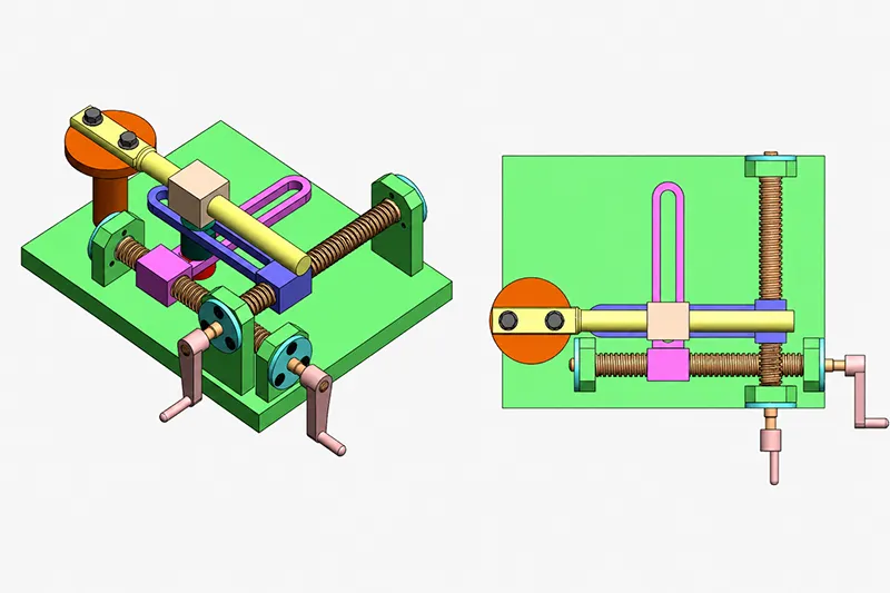
A lead screw mechanism is one of the most practical ways to create controlled linear motion from a rotary input. In a typical assembly, a threaded screw works with a matching nut, bearings, supports, and a manual or motorized drive to move a load with predictable travel per revolution. That is why lead screws remain common in machine tools, positioning stages, automation equipment, lifting devices, medical instruments, and fine-adjustment systems. Their real-world performance depends on thread form, lead, pitch, material pairing, backlash, efficiency, load, speed, lubrication, and manufacturing accuracy. If those variables are chosen poorly, the result can be rapid wear, positioning error, vibration, overheating, or inadequate load capacity. This guide explains how lead screw mechanisms work, which types are available, how to size them, where they are used, and when custom manufacturing is the better choice.
Need a custom lead screw, threaded shaft, nut, or precision motion component? Send us your drawing, material, tolerance, and quantity for a manufacturing review.
What Is a Lead Screw Mechanism?
A lead screw mechanism is a mechanical assembly that converts rotational input into linear output. The screw carries an external thread, the nut carries a matching internal thread, and the thread engagement forces one part to move axially when the other rotates. In most designs, rotating the screw moves the nut along the axis; in others, the nut rotates and the screw translates. The linear distance produced in one full revolution is the lead. Because lead screws rely on sliding contact and thread geometry, they can be used not only for positioning, but also for force transmission, lifting, clamping, and adjustment. Depending on the lead angle, friction, lubrication, and wear condition, some lead screws can also resist back-driving and hold a load without an added brake.
Standard terminology is summarized below. These definitions are used consistently across lead-screw technical references from Nook, Thomson, and related motion-control manufacturers.
| Term | Meaning |
|---|---|
| Lead screw | Threaded shaft that produces linear movement |
| Lead nut | Mating component that travels along the screw |
| Pitch | Axial distance between adjacent thread peaks |
| Lead | Linear travel produced by one screw revolution |
| Backlash | Lost motion between screw and nut during direction reversal |
| Efficiency | Percentage of input torque converted into useful linear force |
A lead screw is not just an ordinary threaded shaft or fastener. Power-transmission threads are designed for repeated motion and load transfer, while standard fastening threads are designed primarily for clamping and joining. That difference affects thread geometry, surface finish, nut design, backlash control, and long-term wear behavior.
How Does a Lead Screw Mechanism Work?
Rotary-to-Linear Motion Conversion
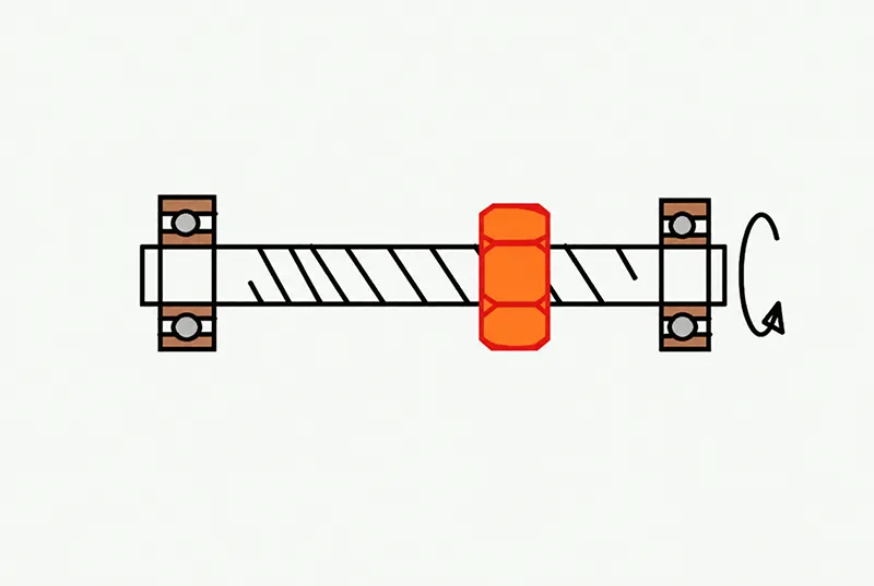
The operating principle is simple: a motor, handwheel, gearbox, or actuator supplies rotary motion; the screw and nut engage through helical threads; and one of the two components is prevented from rotating, forcing axial travel instead. In many systems the screw rotates while the nut is constrained and moves linearly. In other systems, especially some compact actuators, the nut rotates and the screw translates. Closed-loop versions may add an encoder for position feedback, while geared drives may add a gearbox or brake as needed.
Linear Travel per Revolution
The basic travel relation is:
Linear travel = Screw revolutions × Lead
For example, if the lead is 5 mm/rev and the screw turns 20 revolutions, the nut travels 100 mm. For a single-start screw, lead equals pitch; for a multi-start screw, lead equals pitch multiplied by the number of starts.
Speed Relationship
The speed relation is:
Linear speed = Rotational speed × Lead
If a screw rotates at 600 rpm and the lead is 5 mm/rev, the linear speed is 3,000 mm/min. A larger lead gives more travel per turn and therefore higher linear speed. A smaller lead gives finer motion resolution and usually more mechanical advantage. But higher speed is not automatically better, because long screws must still stay below critical speed and within acceptable heat, vibration, and wear limits.
Self-Locking and Back-Driving
A lead screw can be self-locking if friction and thread geometry are sufficient to resist reverse motion under load. Systems with higher efficiency, larger lead angles, or lower-friction lubrication are more likely to back-drive, especially in vertical applications. In practice, self-locking depends on the actual combination of thread angle, coefficient of friction, lubrication condition, wear, and load. High-helix or multi-start screws are often chosen for speed, but that usually reduces or eliminates self-locking. For safety-critical lifting systems, self-locking should never be assumed without calculation and validation testing.
Main Components, Types, and Key Design Parameters
Lead Screw
The lead screw itself determines the system’s lead, pitch, thread form, motion direction, positioning resolution, critical speed, and buckling resistance. Root diameter matters particularly for compressive load, critical speed, and end machining decisions. That is why the screw is not selected by diameter alone; length, end support, required speed, and load direction all matter.
Lead Nut
Nut material and nut style strongly influence friction, wear, noise, backlash, and service life. Common metal options include bronze, brass, steel, and—depending on the power-screw design—cast iron. Common polymer options include acetal/POM, self-lubricating engineered plastics, PTFE-filled compounds, and high-performance plastics such as PEEK for specialized environments. Typical forms include cylindrical nuts, flanged nuts, split nuts, anti-backlash nuts, preloaded nuts, and custom mounting nuts. Anti-backlash designs use spring, cam, or preload features to reduce clearance and improve repeatability.
Bearings and End Supports
End support configuration changes the stiffness and dynamic behavior of the mechanism. Common arrangements include fixed–fixed, fixed–supported, fixed–free, and supported–supported; manufacturers may also describe “supported” as “simple” or “floating.” More rigid support generally raises critical speed capability and column strength, while weaker support lowers those limits. Fixed ends can resist axial, radial, and moment loads, whereas supported ends usually resist axial and radial loads but not moment loads in the same way. In practice, end support directly affects critical speed, axial stiffness, alignment sensitivity, load capacity, and positioning accuracy.
Drive and Coupling Components
Lead screws can be driven by stepper motors, servo motors, handwheels, or gear-reduced drives. System packages may also include flexible or rigid couplings, an encoder for feedback, and a brake for load holding. These supporting components are not accessories in the loose sense; they influence torsional stiffness, alignment tolerance, achievable accuracy, and overall control strategy.
Common Lead Screw Types
Most industrial lead screws use trapezoidal power threads because they balance strength, load capacity, and manufacturability well. Acme is the inch-based common form, while ISO trapezoidal threads are the metric counterpart. Square threads reduce friction and can improve efficiency, but they are harder and more expensive to manufacture accurately. Buttress threads are optimized for very high axial load in one direction. Multi-start screws increase lead without making the thread pitch extremely coarse, which allows faster travel per revolution.
| Lead Screw Type | Main Advantage | Typical Application |
|---|---|---|
| Acme | Strength and manufacturability | Industrial motion systems |
| Trapezoidal | Common metric motion thread | Automation and machine tools |
| Square thread | Higher efficiency | Specialized power transmission |
| Buttress thread | High one-direction load | Presses and lifting equipment |
| Multi-start screw | Faster linear travel | High-speed positioning |
Table note: Acme threads commonly use a 29° included angle, while ISO trapezoidal threads commonly use 30°; square threads are favored where efficiency is critical; buttress threads are used for heavy one-direction thrust; and multi-start screws increase travel per revolution by increasing lead.
Key Lead Screw Design Parameters and Calculations
The most important selection variables are pitch, lead, diameter, unsupported length, axial load, torque, backlash, efficiency, and manufacturing accuracy. For a single-start screw, lead equals pitch. For a multi-start screw, lead equals pitch multiplied by the number of starts. Additional definitions, dimensional terminology, backlash information, and screw-selection data are available in the Nook precision screw technical catalog.
To estimate rotational speed from required travel:
Rotational speed = Required linear speed ÷ Lead
So if the required speed is 2,000 mm/min and the lead is 5 mm/rev, the screw must rotate at 400 rpm.
Axial load should include not only payload, but also guide friction, process force, acceleration, shock, load direction, and safety factor. Required drive torque then depends on load, lead, efficiency, bearing losses, preload, and acceleration. A common first-pass relation is:
Torque ≈ Axial load × Lead ÷ (2π × Efficiency)
That approximation is useful for preliminary sizing, but final motor selection should also include inertia, extra friction, misalignment, duty cycle, and torque margin.
Two structural checks are essential on long screws. First, critical speed: a rotating screw can resonate and whip if speed is too high, and the limit depends on diameter, unsupported length, material, straightness, and end support. Second, buckling load: a compression-loaded screw behaves like a column, so a long, slender shaft can fail by buckling before the material itself yields. The Thomson lead screw technical guide provides critical-speed, column-loading, torque, and sizing references for preliminary system selection. Both checks become especially important in vertical lifting, pressing, or long-stroke systems.
Backlash and positioning accuracy are system-level outcomes rather than thread-only properties. Thread clearance, lead error, straightness, runout, elastic deformation, thermal growth, bearing clearance, coupling compliance, and control compensation all contribute to final motion accuracy. The required manufacturing tolerances should therefore be defined according to the complete mechanism rather than the screw diameter alone.
| Design Requirement | Important Parameter |
|---|---|
| Higher travel speed | Larger lead |
| Finer positioning | Smaller lead |
| Higher axial load | Larger diameter and stronger thread |
| Lower backlash | Preloaded or anti-backlash nut |
| Longer screw | Critical-speed and buckling analysis |
| Better efficiency | Suitable thread geometry and lubrication |
| Higher repeatability | Tight geometry and controlled preload |
Engineering note: These recommendations follow the basic relationships among lead, resolution, load, support stiffness, critical speed, buckling strength, and backlash control used in motion-control sizing guides.
Lead Screw Materials and Manufacturing Methods
Common Screw Materials
Lead screws are commonly produced in carbon steel, alloy steel, stainless steel, and aluminum, depending on load, corrosion exposure, weight, and cost targets. Carbon and alloy steels are common where strength and wear life matter, but they may require heat treatment or a suitable protective surface finish when corrosion, friction, or wear is a concern. Stainless steel is preferred where corrosion resistance, cleanliness, or compatibility with medical, laboratory, food, or chemical environments matters. Aluminum lead screws are used where low weight or non-magnetic behavior is valuable, typically in lighter-duty designs.
Common Nut Materials
Nut selection is a trade-off between friction, PV limits, wear life, noise, lubrication, and cost. Bronze remains a standard choice for wear resistance and higher loads. Brass is easy to machine and works in moderate-load designs. Polymer nuts are attractive for quiet motion, low maintenance, and self-lubricating operation, especially when grease contamination is undesirable. Specialty materials such as PTFE-filled compounds or PEEK-based plastics may be used where temperature, chemical resistance, or low friction justify the extra cost. Anti-backlash designs and special material blends are often the fastest way to improve repeatability without changing the entire screw geometry.
Lead Screw Manufacturing Processes
Lead screws may be made by CNC turning, single-point thread cutting, thread rolling, thread milling, whirling, grinding, straightening, heat treatment, coating, and polishing, depending on volume, tolerance, material, and end-feature requirements. Rolled screws are often the most economical option and can provide good surface strength and smoothness. Machined screws offer flexibility for custom leads, shoulders, grooves, journals, and other non-standard features. Ground screws are used where tighter lead accuracy and surface finish are required. Custom end machining commonly includes bearing seats, shaft shoulders, grooves, flats, keyways, retaining-ring grooves, and coupling features.
Important Inspection Requirements
For production and incoming inspection, the most important checks usually include major and minor diameters, lead accuracy, straightness, runout, thread form, concentricity of end features, backlash, repeatability, and functional travel. Straightness is often measured as total indicator runout, while lead accuracy and backlash are especially important in positioning applications. On assembled systems, journal runout, screw length, and alignment also affect vibration and repeatability, so pure thread inspection is not enough by itself.
Lead Screw vs Ball Screw
Lead screws and ball screws solve the same broad problem—converting rotary motion into linear motion—but they do it in different ways. A lead screw uses sliding contact between the screw and nut, whereas a ball screw uses rolling balls between the screw shaft and nut. According to the official THK ball screw product information, this rolling-contact design provides high efficiency and can require substantially less drive torque than a conventional sliding screw. THK states that a ball screw can require only about one-third of the driving torque of a conventional sliding screw.
| Factor | Lead Screw | Ball Screw |
|---|---|---|
| Motion principle | Sliding friction | Rolling ball contact |
| Efficiency | Moderate to low | High |
| Backlash | Depends on nut design | Can be preloaded very low |
| Cost | Generally lower | Generally higher |
| Noise | Often quiet | May produce more mechanical noise |
| Self-locking | Possible in some designs | Usually back-drivable |
| Speed | Moderate | Higher |
| Maintenance | Often simple | Requires clean lubrication |
| Contamination tolerance | Often better | More sensitive |
| Precision | Moderate to high | High to very high |
Table note: Ball screws achieve higher efficiency because of rolling contact, while lead screws trade efficiency for lower cost, simpler construction, quieter motion, and possible self-locking. Lead screws can also be a better fit in dirty or lightly contaminated environments because they do not rely on recirculating balls in the same way.
Choose a lead screw when the application values moderate speed, quiet motion, lower cost, simpler construction, manual adjustment, or some degree of load-holding behavior more than maximum efficiency. Choose a ball screw when the axis needs high speed, high duty cycle, very low backlash, and high repeatability—especially in CNC or automation axes where energy efficiency and precision justify the higher system cost.
Choosing between a lead screw and a ball screw should be based on load, speed, accuracy, duty cycle, environment, and total system cost—not component price alone. Thomson’s own selection guidance emphasizes those trade-offs, including cost, speed, stroke, backlash, accuracy, and environmental constraints.
How to Select the Right Lead Screw Mechanism
A good buying process starts with the motion requirement, then checks load, thread form, geometry, support method, backlash target, material, and manufacturability. Manufacturer sizing workflows consistently recommend balancing load, speed, stroke, backlash, accuracy, and environment before choosing the final screw concept.
| Selection Step | What to Define |
|---|---|
| Define the required motion | Total travel, linear speed, positioning resolution, repeatability, direction changes, horizontal or vertical move |
| Calculate the load | Static load, dynamic load, acceleration, friction, impact, safety factor |
| Select lead and thread type | Fine vs fast travel, single-start vs multi-start, self-locking requirement, thread standard, efficiency target |
| Choose diameter and support method | Screw length, installation space, bearing spacing, support arrangement, buckling resistance, critical speed |
| Define accuracy and backlash | Lead accuracy, repeatability, axial play, maximum backlash, preload, straightness, runout |
| Choose materials and surface treatment | Wear, corrosion, lubrication, temperature, cleanliness, target life |
| Review manufacturing and assembly details | Bearing seats, coupling features, end threads, keyways, grooves, cross holes, flanges, nut mounting, lubrication access, covers |
| Prototype and validate | Running torque, backlash, noise, heat rise, load capacity, positioning accuracy, wear, duty cycle |
The table below turns common application conditions into a practical design direction.
| Application Condition | Recommended Direction |
|---|---|
| High axial load at low speed | Acme or trapezoidal screw |
| Fast linear travel | Larger-lead or multi-start screw |
| Minimal backlash | Preloaded anti-backlash nut |
| Vertical lifting | Verify self-locking, buckling, and brake strategy |
| Corrosive environment | Stainless steel or protected alloy steel |
| Low-noise equipment | Polymer nut with suitable lubrication strategy |
| Long rotating screw | Review critical speed and support arrangement |
Common Problems, Solutions, and Applications
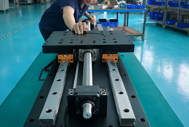
Lead screw failures are often blamed on the screw or nut, but many are actually caused by system-level issues such as poor alignment, weak end support, wrong preload, contamination, or incorrect lubrication. Vibration, heat, noise, backlash growth, and premature wear usually make sense only when the full mechanism—including bearings, guides, coupling, and motor behavior—is reviewed together.
| Problem | Likely Cause | Recommended Solution |
|---|---|---|
| Excessive backlash | Thread clearance or nut wear | Use anti-backlash nut or replace worn components |
| Positioning error | Lead error, backlash, or misalignment | Improve manufacturing accuracy and assembly alignment |
| High operating torque | Poor lubrication, excessive preload, or misalignment | Review lubricant, nut fit, and bearing alignment |
| Screw vibration or whipping | Excessive speed or unsupported length | Reduce speed or improve support configuration |
| Rapid thread wear | Wrong material pair or contamination | Improve materials, lubrication, and protection |
| Nut binding | Bent screw or poor alignment | Check straightness, supports, and assembly |
| Excessive heat | High speed, friction, or overload | Reduce load, review lubrication, and verify efficiency |
| Corrosion | Unsuitable material or finishing | Use stainless steel or protective coating |
| Load moves backward | Back-drivable screw | Add brake, gearbox, or locking feature |
| Screw buckles | Excessive compressive load | Increase diameter or improve end support |
Troubleshooting note: Backlash, torque, vibration, wear, buckling, and heat all connect directly to thread clearance, preload, material pairing, lubrication, end support, straightness, and critical speed limits.
Lead screw mechanisms appear in many industries because they balance control, force multiplication, compact packaging, and customizability well. In CNC and machine-tool settings, they are used for manual axis adjustment, fixtures, slides, and smaller machine axes. In industrial automation, they are common in linear actuators, packaging machinery, adjustable guides, and inspection equipment. In medical and laboratory equipment, they are used for patient positioning, diagnostics, syringe pumps, and laboratory stages. Precision lead screws are also used in optics, XY stages, semiconductor equipment, and selected automotive or aerospace actuation tasks where compact, repeatable linear motion is required.
Custom Lead Screw Manufacturing, Conclusion, and FAQs
When Custom Manufacturing Makes Sense
Standard lead screws work well in many designs, but custom manufacturing becomes necessary when the application needs a non-standard lead or pitch, unusual thread form, very long or short overall length, integrated shoulders or bearing seats, special end machining, tight straightness or runout limits, custom nut geometry, corrosion-resistant material, heat treatment, coating, or prototype-to-low-volume quantities. An early DFM review can identify machining risks, inspection difficulty, excessive tolerance requirements, and opportunities to reduce cost before production. Many lead-screw suppliers explicitly offer custom threads, materials, end machining, and matched assemblies because standard catalog parts do not cover every motion envelope or mounting interface.
Information to Include in an RFQ
A strong RFQ reduces quoting delays and prevents expensive revisions later. The most useful package includes a complete 2D engineering drawing, a 3D model where available, functional requirements, operating conditions, and inspection targets—not only the thread callout.
| RFQ Item | What to Provide |
|---|---|
| Design data | 2D drawing, 3D model if available |
| Screw specification | Material, thread type, major diameter, pitch, lead, number of starts, thread direction |
| Overall geometry | Overall length, threaded length, journals, shoulders, grooves, end threads, keyways, holes, flats |
| Nut specification | Nut material, nut style, mounting details, preload or backlash target |
| Accuracy requirements | Lead accuracy, straightness, runout, concentricity, surface roughness |
| Process requirements | Heat treatment, coating, lubrication plan, packaging, traceability if needed |
| Functional conditions | Load, speed, duty cycle, orientation, environment, contamination, temperature |
| Commercial data | Prototype quantity, production quantity, annual demand |
Need a Custom Lead Screw or Nut?
Send us your drawing, load, speed, material, tolerance, and order quantity. Our engineering team can review thread manufacturability, end machining, material selection, backlash requirements, and inspection needs before quotation.
Conclusion
A lead screw mechanism converts rotary motion into linear movement through the interaction of a threaded screw and matching nut. Its real performance depends on more than thread size alone: lead, pitch, thread form, diameter, nut material, backlash, lubrication, support stiffness, speed, and load all matter. Acme, trapezoidal, square, buttress, and multi-start screws each serve different motion and force requirements, and proper selection should always include torque, critical speed, buckling resistance, positioning accuracy, duty cycle, and environmental conditions. Standard parts are often enough for general adjustment or motion tasks, but custom machining may be necessary when the design needs special leads, end features, materials, coatings, or tighter tolerances. The earlier these requirements are reviewed, the easier it is to avoid wear, misalignment, excessive torque, vibration, and expensive redesign during production.
Upload your 2D or 3D files to request a lead screw quotation for custom lead screws, threaded shafts, matching nuts, and precision linear-motion components. Include your material, pitch, lead, number of starts, overall length, tolerance, load, speed, and required quantity for a faster engineering review.
FAQs About Lead Screw Mechanisms
What is a lead screw mechanism used for?
It is used to convert rotary motion into controlled linear movement for positioning, lifting, clamping, adjustment, and force transmission. Typical examples include machine tools, linear actuators, medical devices, and laboratory equipment.
What is the difference between pitch and lead?
Pitch is the axial distance between adjacent threads. Lead is the linear distance traveled in one revolution. They are equal on a single-start screw, but on a multi-start screw the lead equals pitch multiplied by the number of thread starts.
Can a lead screw mechanism be self-locking?
Yes, some lead screws can resist back-driving because of friction and thread geometry. But self-locking depends on the actual lead angle, coefficient of friction, lubrication, wear, and load, so it should be verified for the real operating condition.
What causes backlash in a lead screw?
Backlash mainly comes from clearance between the screw and nut, manufacturing tolerances, wear, insufficient preload, and system-level factors such as runout, straightness, and assembly misalignment. Anti-backlash or preloaded nuts are commonly used to reduce it.
When is a custom lead screw required?
A custom lead screw is often required when the design needs a non-standard lead, special material, unusual overall length, integrated end features, low backlash, tight runout, special nut geometry, or application-specific mounting details that standard catalog screws cannot provide.

