
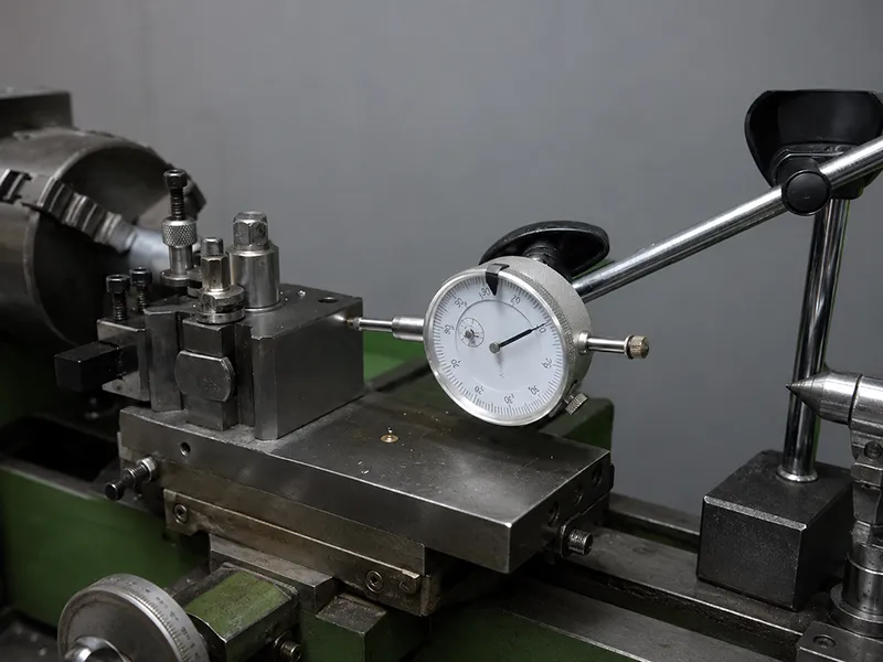
Depth of cut is one of the most important parameters in the CNC machining process because it determines how much material the tool removes in a single pass. That single choice directly influences cutting force, spindle load, torque, heat generation, chip formation, tool deflection, material removal rate, surface finish, and tool life. When depth of cut is too large, the result can be chatter, insert breakage, dimensional error, unstable chips, or even machine overload. When it is too small, productivity suffers, cycle time increases, and the tool may rub instead of forming a stable chip. In practice, the “right” DOC depends on the operation, workpiece material, cutter or insert geometry, usable cutting-edge length, machine power, setup rigidity, workholding, chip evacuation, and whether the goal is roughing or finishing. The best setting is not the deepest possible cut, but the deepest stable cut that still protects accuracy, finish, tool life, and cost per part.
If your team is comparing process windows for a new part, this article is written to help engineers, buyers, and machinists choose a DOC that is productive and safe enough for real production.
What Is Depth of Cut in Machining
Depth of cut, usually written as DOC or aₚ in many machining references, is the amount of material removed by the cutting tool in one pass. In turning, it is a radial thickness removed from the workpiece; in milling, it is typically split into axial depth of cut and radial depth of cut. It is normally specified in millimeters or inches, and increasing it usually raises metal removal rate, cutting force, and spindle load.
Depth of cut should not be confused with other machining variables. Feed rate describes how far the tool advances in a unit of time, or in turning, how far it advances per spindle revolution. Cutting speed describes the relative surface speed between the cutting edge and the workpiece. Total machining depth is the full amount of material that must be removed to reach the final feature, while depth of cut is only the amount removed in one pass. Sandvik’s machining definitions distinguish feed, cutting speed, and axial/radial depth of cut as separate variables because they affect chip formation and process stability in different ways.
A simple example makes the distinction clear. If a pocket must reach 12 mm total depth and the tool is programmed to cut 3 mm axial DOC per pass, the roughing operation requires four depth passes. If the programmer leaves finishing stock, the total number of toolpath levels may be higher, but the DOC per pass is still 3 mm, not 12 mm.
How to Calculate Depth of Cut in Turning
In external turning, DOC is calculated from the change in workpiece diameter:
DOC = (Initial diameter − Final diameter) ÷ 2
The reason for dividing by two is straightforward: turning depth is measured radially, so a given radial DOC changes the workpiece diameter by twice that amount. The official Sandvik turning formulas and definitions provide additional reference information for cutting depth and other turning parameters.
Turning DOC Calculation Example
Suppose the initial diameter is 50 mm and the diameter after one pass is 46 mm.
DOC = (50 − 46) ÷ 2 = 2 mm
So the radial depth of cut is 2 mm. That means the turning tool removed 2 mm from the workpiece radius, even though the measured diameter changed by 4 mm.
Internal Boring Calculation
For internal boring, the same radial logic applies:
DOC = (Final bore diameter − Initial bore diameter) ÷ 2
Sandvik’s boring definitions describe cutting depth as the difference between the uncut and cut hole radius, which is why bore growth is also divided by two when you calculate DOC from diameters.
Example:
- Initial bore diameter: 20 mm
- Final bore diameter: 24 mm
DOC = (24 − 20) ÷ 2 = 2 mm
So the boring tool removes 2 mm radially.
Multiple Turning Passes
If the total radial stock allowance is larger than the DOC you choose for one pass, the roughing pass count can be estimated as:
Number of passes = Total radial stock allowance ÷ DOC per pass
In production, that result is often adjusted because roughing and finishing are not the same strategy. Sandvik explicitly treats roughing and finishing as different application methods, and Seco emphasizes that consistent finish stock improves surface finish, tool life, and stability in the final pass. In other words, a mathematical pass count is only the starting point; a realistic process plan usually reserves a controlled finishing allowance.
How to Determine Depth of Cut in Milling
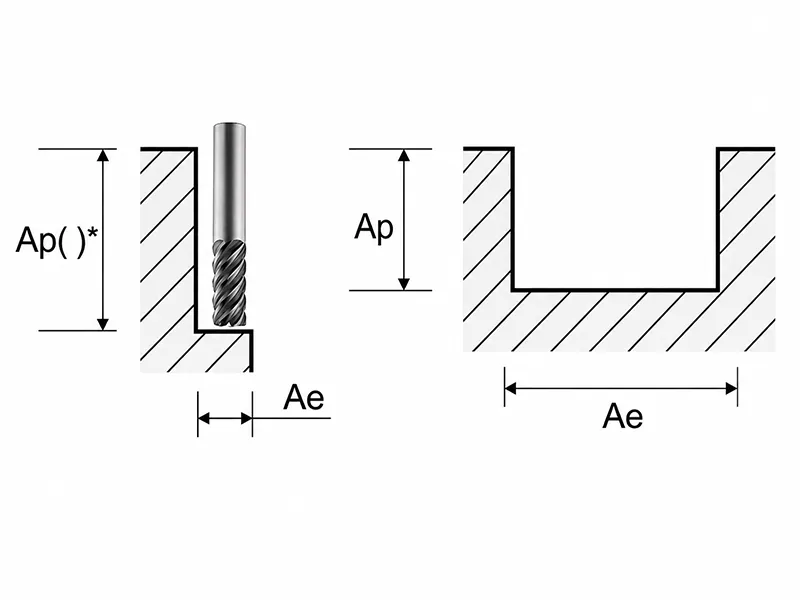
Milling is more nuanced than turning because “depth of cut” often has two engagement dimensions instead of one. Sandvik’s milling formulas define aₚ as axial depth of cut and aₑ as radial depth of cut. Many shops also call radial DOC stepover or width of cut. Both matter because they change chip thickness, force direction, heat concentration, and the number of teeth engaged in the cut.
Axial Depth of Cut
Axial depth of cut, or aₚ, is the engagement measured parallel to the cutter axis. In practice, this is the layer thickness removed in a pocket, the vertical depth of an end mill below the original surface, or the amount of sidewall height being machined in one pass.
Radial Depth of Cut
Radial depth of cut, or aₑ, is the sideways engagement of the cutter into the material. In slotting, aₑ is close to the cutter diameter. In side milling, it may be only a fraction of the cutter diameter. In adaptive or high-efficiency milling, radial engagement is intentionally kept small while axial engagement is increased to spread heat and wear over more usable flute length.
Milling DOC Example
Assume a pocket must reach a total depth of 15 mm and the roughing strategy uses 3 mm axial DOC.
Number of passes = 15 ÷ 3 = 5 passes
If you plan to leave 0.5 mm for finishing, then the roughing levels should stop short of the final floor so the finish pass removes that remaining stock predictably rather than absorbing an uneven load. Consistent finish stock is a recurring recommendation in modern milling guidance because it stabilizes tool pressure and helps surface finish.
Axial and Radial Engagement Working Together
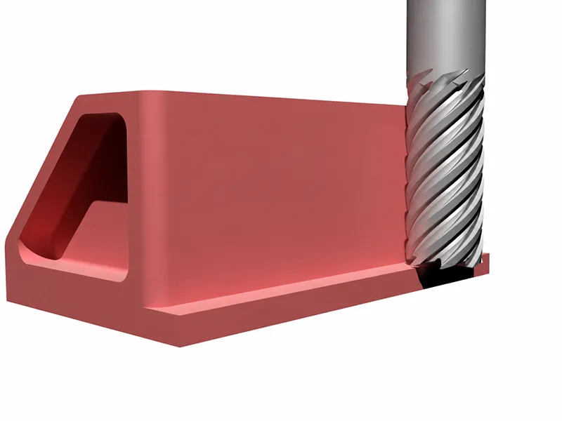
Large aₚ increases the length of cutting edge engaged. Large aₑ increases chip thickness and cutter load. Full-width slotting therefore usually demands a smaller axial DOC, lower feed, or both. Light side milling can often support deeper axial engagement because the radial engagement is limited. Sandvik, Seco, and Harvey-style high-efficiency milling guidance all point in the same direction: when radial engagement is reduced and chip thickness is managed correctly, deeper axial cuts can be practical and productive.
Depth of Cut in Drilling Reaming and Grinding
DOC is not interpreted the same way in every process. In drilling, the programmer usually specifies hole depth directly. In reaming, the tool removes a small allowance left in the hole. In grinding, the infeed is typically much smaller than in turning or milling because heat control and surface integrity become dominant concerns.
Drilling
Sandvik’s drilling guidance starts with three core questions: hole diameter, hole depth, and hole quality. That is a useful reminder that drilling is usually programmed as a Z-depth operation, not as a radial DOC formula. Depth planning must include drill-point geometry, breakthrough distance, blind-hole clearance, tool type, and chip-evacuation strategy. The programmed Z-depth may need to exceed the required cylindrical hole depth so the full drill diameter reaches the specified position. For through-holes, Sandvik recommends extending beyond the exit by approximately point length + 1 mm so the drill point fully clears the part.
For blind holes, the programmed depth often has to exceed the required full-diameter cylindrical depth because the drill point is conical rather than flat. When chip evacuation becomes difficult, pecking strategy, coolant direction, and flute space matter. Sandvik recommends directing coolant close to the tool axis for external-coolant drilling, and its deep-hole drilling tools highlight flute geometry and coolant flow as major contributors to chip evacuation and torque control. Kennametal also warns that drilling setups that generate heat without proper chip removal can work-harden the material.
Reaming
Reaming removes only a small amount of stock, but that small allowance is exactly what lets the process improve bore size, roundness, surface finish, and consistency. The reaming allowance must be large enough for the cutting edges to remove material rather than merely rub or burnish the bore. However, excessive allowance can increase tool load, chip volume, and the risk of poor hole quality. The official Kennametal reaming guide provides further guidance on stock allowance, cutting action, speed, feed, and reaming performance. Its reaming guidance also gives rule-of-thumb allowances by hole size and recommends lower speed but higher feed than drilling so the reamer actually shears material instead of burnishing it.
Grinding
Grinding uses much smaller infeed values than most turning and milling operations because the process is highly sensitive to heat, wheel condition, and contact pressure. When a finer finish is required, the Norton grinding surface-finish guidance recommends reviewing depth of cut, feed rate, wheel speed, dressing condition, and spark-out passes., and it notes that excessive heat in grinding can lead to burning, burnishing, grooves, or even sub-surface cracking. Norton’s technical grinding references also explain that as abrasive points dull, friction and heat rise, which is why light, controlled passes and proper dressing are often necessary for precision surfaces.
Factors That Determine the Correct Depth of Cut
There is no universal DOC that works for every part. The correct setting is always conditional because cutting behavior changes with material, tool design, machine capability, setup stiffness, engagement pattern, and thermal control. Sandvik’s turning and milling guidance repeatedly starts with the same questions: what is the operation, how rigid is the setup, can the component be fixed securely, is chip evacuation critical, and what are the power and stability limits of the machine.
Workpiece material is the first major filter. Softer materials such as aluminum and mild steel generally allow more aggressive cuts than stainless steel, superalloys, or hardened materials under otherwise similar conditions. Kennametal explicitly notes that harder, tougher materials often require smaller DOC or lighter feed, while stainless steels and high-temperature alloys are especially prone to work hardening if the cut rubs instead of shears. Titanium is also sensitive to engagement strategy: Sandvik notes that large radial cuts in titanium can hurt tool life, and plastics demand heat control because machining heat can cause melting or chip welding.
The cutting tool sets hard physical limits. Tool diameter, flute count, insert geometry, corner radius, tool material, coating, and especially usable cutting-edge length all matter. Sandvik’s ISO 13399 parameter list includes maximum cutting depth fields such as APMX and CDX, while individual tool pages often publish maximum practical DOC values or maximum length-of-cut limits. In simple terms: do not program an end mill deeper than its usable flute length, and do not ask an insert to cut beyond the edge length and force range it was designed for.
Machine rigidity and power are the next gate. Sandvik lists stability, power, and torque among the key machine considerations for turning, and its milling guidance adds spindle size, power, cutter size, and balanced holders. Seco’s vibration guidance is even more direct: increasing overhang raises bending and vibration risk sharply, while shorter tools and larger diameters reduce it.
Workholding is equally important. A rigid machine cannot rescue a weak setup. Sandvik repeatedly asks whether the component can be fixed securely, and both Sandvik and Seco note that thin-walled or unstable parts need lower cutting force strategies, smaller cutting data, and attention to force direction to avoid chatter, bending, and geometric error.
Toolpath and engagement also change what DOC is safe. Straight plunges, sharp corners, sudden engagement changes, and centerline cutter positions can produce thicker chips at entry or exit and trigger vibration. Sandvik recommends smooth entry, roll-in motion where appropriate, and attention to cutter positioning and corner engagement because these factors directly influence chip thickness and tool life.
Finally, coolant and chip evacuation cannot be treated as an afterthought. Sandvik defines the primary functions of cutting fluid as chip evacuation, cooling, and lubrication. On deep holes and heavy cuts, poor chip evacuation means recutting, heat concentration, chip packing, and process instability. External coolant direction, through-tool coolant, flute space, and chip-breaking strategy all influence how much DOC a setup can sustain safely.
How Depth of Cut Affects Machining Performance
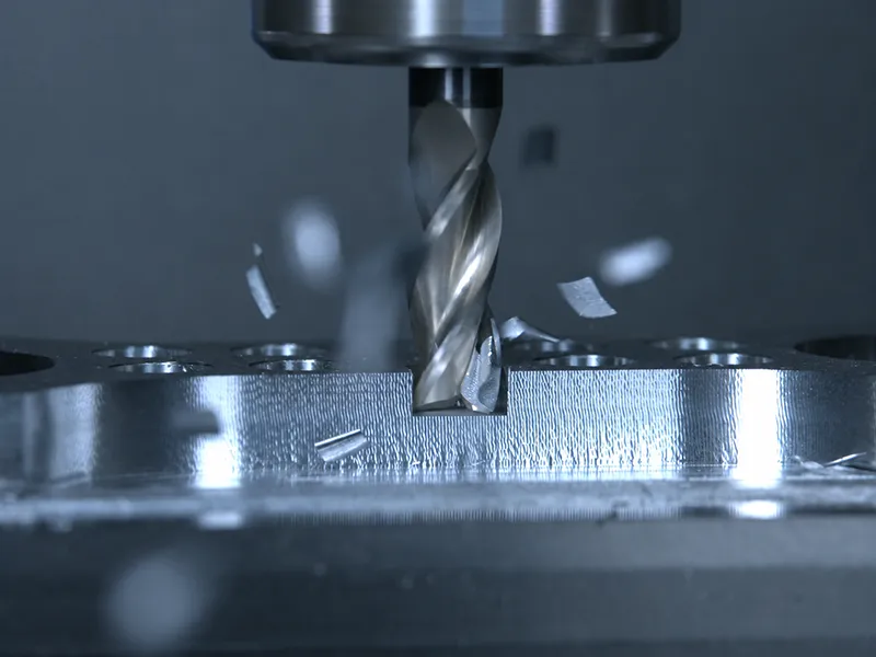
The most direct effect of increasing DOC is that more material enters the cut. That typically raises cutting force, spindle load, torque demand, and fixture load. Sandvik’s turning guidance identifies depth of cut as one of the three main machining parameters, and when turning DOC is too deep it warns of high power consumption, insert breakage, and increased cutting forces. In milling, Sandvik and other tooling references define material removal rate as a function of depth, width, and feed, so larger DOC can improve throughput when the machine and setup can handle the load.
For milling, the common production relation is:
MRR = Width of cut × Depth of cut × Feed rate
Sandvik and educational machining references describe MRR as the volume removed per unit time and show that it is established from cutting depth, width, and feed. That is why increasing DOC often shortens cycle time. But the productivity gain is real only if chip evacuation, spindle power, temperature, and vibration remain under control.
More DOC also means more opportunity for deflection. Sandvik’s vibration guidance for milling explains that long overhangs create deflection risk, and Seco shows that overhang strongly affects bending behavior. In practical shop terms, higher forces can push the tool off path, leave tapered walls, change floor flatness, or create uneven remaining stock for finishing. If the part is thin-walled, the workpiece may deflect as much as the tool does.
Tool life is affected in both directions. A DOC that is too large can overload the edge and accelerate chipping or breakage. But a DOC that is too small can also be harmful if it causes rubbing, unstable chip formation, or excessive heat. Sandvik explicitly notes that too-small turning depth of cut can reduce chip control, increase vibration, add heat, and become uneconomical. Kennametal makes the same point in work-hardening materials: if the tool rubs instead of cuts, heat rises and the process gets less stable.
Surface finish typically improves when finishing is separated from heavy roughing. Heavy cuts can leave deflection marks, vibration patterns, and nonuniform stock. Norton’s grinding guidance shows the same general principle in abrasive finishing: lighter cuts and controlled spark-out improve surface integrity. In milling and turning, leaving a consistent finish allowance gives the final pass a stable load and usually produces better dimensional accuracy and appearance.
Roughing Finishing and a Practical DOC Selection Workflow
Roughing and finishing should not use the same DOC strategy because they have different goals. Roughing is designed to remove material efficiently, so the priorities are metal removal rate, stable chip evacuation, acceptable spindle load, and enough remaining stock for a predictable finishing pass. Finishing is designed to achieve final size, tolerance, form, and surface quality, so the priorities are consistency, lower force variation, and predictable tool behavior. Sandvik and Seco both emphasize the value of controlled finish stock rather than “taking everything in roughing.”
A finishing pass should be small and consistent, but not so light that the tool only rubs. Sandvik warns against very small DOC in turning because of heat and vibration, and Kennametal warns that in materials prone to work hardening, light rubbing passes can make the surface harder and less predictable. On thin walls, Sandvik also recommends aligning force direction carefully and using sharp tools with appropriate nose radius so the finish pass does not bend the part.
If you want the article to convert inquiry traffic, this is the point where a commercial site can place a helpful call to action without sounding promotional: Need help choosing roughing DOC, finish allowance, and feeds/speeds for a production part? Our machining team can review your drawing, material, tolerance targets, and wall thickness to recommend a stable process window before quoting.
The workflow below synthesizes manufacturer guidance on tool limits, engagement control, finish stock, vibration, and chip evacuation into a practical selection method.
Identify the operation. Decide whether the cut is turning, face milling, slotting, pocketing, side milling, drilling, reaming, grinding, roughing, semi-finishing, or finishing. The safe DOC range changes immediately when the engagement style changes.
Check toolmaker limits first. Review maximum axial depth, radial engagement guidance, usable edge length, flute length, and any published power or holder requirements. If the tooling data says 3×D maximum DOC or a specific APMX/CDX value, that limit is more important than generic rules of thumb.
Evaluate the material honestly. Softer materials often tolerate deeper or wider cuts; stainless, titanium, heat-resistant alloys, and hard materials usually demand more conservative DOC or more careful engagement control.
Check rigidity before you chase MRR. Short tool overhang, strong workholding, and stable spindle power almost always matter more than theoretical DOC. If the setup is weak, reduce engagement before you increase feed or speed.
Define stock allowances. Decide how much material roughing removes, whether semi-finishing is needed, and what consistent finishing stock should remain.
Run a controlled trial. Watch spindle load, sound, chip shape, vibration, temperature, wear pattern, and part dimensions. Machine response is often the fastest truth source.
Optimize gradually. Increase DOC only when the process remains quiet, chip evacuation stays reliable, dimensions remain stable, and wear is predictable.
The decision table below is a practical way to present that logic on a service page.
| Machining condition | DOC direction |
|---|---|
| Rigid machine and short tool | Larger DOC may be possible |
| Long tool overhang | Reduce DOC |
| Full-width slotting | Reduce DOC or lower feed |
| Light side milling | Deeper axial DOC may be possible |
| Thin-wall component | Use smaller, balanced cuts |
| Finishing operation | Use controlled finishing allowance |
| Hard or work-hardening material | Reduce DOC according to tooling and stability |
That guidance follows published recommendations on overhang, thin walls, force direction, slotting engagement, and finish stock control.
Practical troubleshooting is just as important as the initial calculation, because DOC should never be selected in isolation. It must be evaluated together with feed, cutting speed, radial engagement, tool geometry, machine power, coolant strategy, and setup rigidity.
| Mistake | Possible result | Better practice |
|---|---|---|
| Not dividing diameter change by two in turning | DOC calculated twice as large | Use the radial turning formula |
| Confusing total feature depth with depth per pass | Overload or excessive passes | Separate feature depth from pass depth |
| Ignoring radial engagement in milling | Unexpected cutter load | Evaluate both aₚ and aₑ |
| Using the same DOC for every material | Rapid wear or low productivity | Adjust for material behavior |
| Exceeding flute length or usable edge length | Rubbing, collision, instability | Check toolmaker maximum cutting depth |
| Ignoring overhang | Chatter and deflection | Shorten assembly or reduce engagement |
| Removing all stock in roughing | Unstable finish pass | Leave a controlled finish allowance |
| Taking an extremely light finish pass | Rubbing, heat, poor finish | Stay above the practical minimum chip-forming level |
| Increasing DOC without checking spindle load | Machine overload | Trial incrementally and monitor load |
| Ignoring chip evacuation | Chip packing and tool failure | Improve coolant, flute space, and toolpath |
The table above is consistent with turning geometry references, Sandvik’s DOC and vibration guidance, Kennametal’s work-hardening and reaming recommendations, and Norton’s warnings about heat and dull cutting conditions.
Conclusion
Depth of cut is the amount of material removed in a single machining pass, but calculating it correctly depends on the process. In turning, DOC is half the change in diameter because the tool removes material radially. In milling, DOC is not just one number: axial depth (aₚ) and radial engagement (aₑ) must be evaluated together. A larger DOC can improve material removal rate and reduce cycle time, but it also raises cutting force, power demand, heat, and deflection risk. That is why roughing and finishing need different strategies, and why the best setting depends on material, tooling, machine rigidity, workholding, chip evacuation, and quality requirements. The most profitable DOC is usually not the maximum your spindle can survive for one pass. It is the deepest stable cut that still delivers acceptable tool life, dimensional control, surface finish, and overall manufacturing cost.
FAQ About Depth of Cut in Machining
How is depth of cut calculated in turning
Subtract the final diameter from the initial diameter and divide by two. That gives the radial DOC, which is the value used in turning practice.
What is the difference between axial and radial depth of cut
Axial DOC is measured parallel to the cutter axis and represents how deep the tool cuts vertically. Radial DOC measures how much of the cutter diameter is engaged sideways in the cut. Sandvik defines these as aₚ and aₑ respectively.
Does a larger depth of cut reduce machining time
It often can, because larger DOC increases material removal rate and may reduce the number of passes. But the time savings only hold if the machine, tool, fixture, and chip evacuation system can support the added load without chatter, excess heat, or unstable wear.
Can the depth of cut be too small
Yes. DOC that is too small can lead to rubbing, excessive heat, poor chip control, work hardening in difficult materials, unstable finish, and unnecessary cycle time. Sandvik notes these risks directly for turning, and Kennametal points to rubbing as a common cause of heat and work hardening.

