
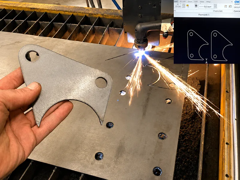
Custom manufacturing is the practice of making parts or products to a company’s own design requirements rather than buying standard catalog items. In product development, that usually means turning CAD models, drawings, prototypes, and low-volume demand into physical parts that can be tested, revised, and eventually launched. It is especially valuable for one-offs, engineering validation, bridge production, special materials, and geometries that standard products do not cover.
What Is Custom Manufacturing
In practical product-development terms, custom manufacturing means producing parts directly from a customer’s specifications such as a 3D CAD model, 2D drawing, required material, tolerance, finish, and order quantity. Rather than selecting an off-the-shelf component, the buyer defines the geometry and performance requirements and the manufacturer chooses the process route needed to make it. Official digital-manufacturing guidance from Protolabs describes parts being made directly from the customer’s 3D CAD model, while Formlabs frames custom manufacturing as designing, engineering, and producing goods to unique customer specifications, including one-offs and short runs.
That flexibility is what makes custom manufacturing central to product development. It can support concept models, functional prototypes, housings, brackets, fixtures, machine components, sheet metal enclosures, specialty medical parts, aerospace components, and replacement or niche industrial parts where catalog sourcing is not enough. CNC machining guidance from Protolabs, for example, highlights applications such as housings, enclosures, brackets, fixtures, gears, bearings, internal mechanical components, and medical instrumentation, while its broader FAQ notes regular use across medical device, automotive, aerospace, electronics, consumer product, and technology projects.
| Manufacturing type | Main characteristic | Best fit |
|---|---|---|
| Catalog or standard manufacturing | Sourcing existing parts built to standard specifications | Commodity parts, routine replacements, simple procurement |
| Custom manufacturing | Producing parts to a customer’s own geometry, material, tolerance, and finish requirements | Prototypes, unique components, low-volume production, specialized products |
| Mass production | High-volume output using stable tooling and repeatable processes | Mature products with steady demand and proven designs |
This comparison is a practical sourcing framework synthesized from official guidance on custom manufacturing, low-volume production, and tooling-based production economics rather than a formal ISO product taxonomy.
Why It Matters in Product Development
Product development rarely begins with a design that is immediately ready for large-scale manufacture. Autodesk design for manufacturing guidance emphasizes that manufacturing constraints should be considered early so teams can improve process efficiency, cost control, and production readiness. In other words, custom manufacturing is not just a way to “make a part”; it is the mechanism that lets engineering teams learn quickly from real hardware before expensive commitments are made.
This matters most in the stages between concept and scale-up. Protolabs’ low-volume production guidance describes low-volume manufacturing as a bridge from prototyping to production, helping teams test critical parts before committing to larger quantities while reducing inventory risk, upfront manufacturing cost, and supply-chain rigidity. Formlabs similarly describes low-volume manufacturing as a route for rapid, cost-efficient production of custom end-use parts, especially when demand is uncertain or designs are still evolving.
For startups, R&D teams, and industrial OEMs, that bridge can be decisive. A prototype can confirm fit and function, a pilot batch can support field trials or market feedback, and a low-volume run can supply early customers or replacement-part demand while the final production strategy is still being refined. That is why custom manufacturing often sits at the center of modern product-development workflows even when the eventual end state is injection molding, casting, forging, or another high-volume process.
Common Custom Manufacturing Processes
No single manufacturing method is “best” for every product. The right choice depends on geometry, material, tolerance, surface requirements, quantity, and how far the design has progressed. In practice, most product teams compare a small group of processes: CNC machining, sheet metal fabrication, additive manufacturing, injection molding, and, where strength or shape demands justify it, casting or forging.
CNC machining is a subtractive process. Official Protolabs guidance describes CNC milling as cutting solid plastic and metal blocks into final parts using 3-axis and indexed 5-axis processes, while CNC turning machines cylindrical features from rod stock. Siemens’ CAM documentation adds that part models are converted into machine instructions that optimize feed, speed, and tool selection. This makes CNC machining for custom parts especially useful for precise metal and engineering-plastic parts, prototypes, housings, brackets, and low-volume end-use components.
Sheet metal fabrication is typically the right fit when the part begins as sheet and needs cutting, punching, bending, or welded assembly. TRUMPF’s sheet metal guidance notes that industries use laser cutting, punching, and bending to process thin-sheet components with numerous bends and complex contours, while Protolabs highlights typical follow-on services such as welding, hardware insertion, and powder coating. That makes it a strong choice for enclosures, covers, brackets, cabinets, and structural panels.
Additive manufacturing builds parts by successive addition of material. The ISO/ASTM 52900 additive manufacturing definition describes additive manufacturing as creating physical objects from 3D model data by successively adding material, which is why it is useful for rapid prototypes, fit-check parts, and complex geometries. In product development, additive manufacturing is usually most valuable for rapid prototypes, fit checks, complex shapes, and certain customized end-use parts where tooling would be too slow or too costly.
Injection molding is the dominant route when a plastic design is stable enough to justify tooling. Protolabs’ injection-molding guide explains that the process starts by machining metal tooling, then injecting molten resin into the tool to form the final part. The same guidance also notes that tooling cost is the main cost determinant and that molding becomes more economical as quantity rises because the mold cost is amortized over more parts. That makes injection molding less attractive for very early uncertainty, but strong for repeatable plastic production once the design is mature.
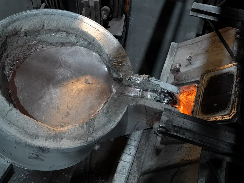
Casting and forging remain important when part geometry or mechanical performance points away from purely machined-from-solid parts. The American Foundry Society defines metalcasting as pouring molten metal into a mold to create geometrically complex parts, while the Forging Industry Association defines forging as pressing, pounding, or squeezing metal under high pressure into high-strength parts. In product development, both processes are often paired with follow-up machining to finish critical surfaces and tolerances.
| Process | Strongest fit in product development | Main advantage | Main trade-off |
|---|---|---|---|
| CNC machining | Functional prototypes, precision custom parts, low-volume metal or plastic components | High accuracy, broad material range, no mold tooling | Material removal can make complex geometry or very high volumes less economical |
| Sheet metal fabrication | Enclosures, panels, brackets, fold-up housings | Efficient for thin walls, bends, and structural sheet parts | Best suited to sheet-based designs rather than thick solid geometry |
| 3D printing | Visual models, fit checks, rapid iterations, complex internal geometry | Fast design iteration and low setup burden | Material, tolerance, and end-use strength depend heavily on process |
| Injection molding | Mature plastic parts moving toward larger repeat volumes | Excellent repeatability and low per-part cost at scale | Upfront tooling cost and redesign sensitivity |
| Casting or forging | Complex metal shapes or very high-strength blanks | Shape capability or mechanical performance benefits | Tooling and secondary machining are often required |
The comparison above synthesizes official process descriptions and product-development guidance from ISO, AFS, FIA, TRUMPF, Siemens, and Protolabs.
From Design to Finished Part
A typical custom manufacturing workflow follows a predictable path: CAD design → DFM review → material selection → quotation → prototype → testing and revision → production → inspection → delivery. The exact sequence varies by process, but the basic logic is the same across machining, molding, additive, and fabrication: create manufacturable data, validate the physical outcome, then scale only after the design performs as intended. Autodesk’s DFM guidance, Siemens’ CAM documentation, and Protolabs’ production workflow material all reflect this design-to-manufacture structure.
The files that start that workflow matter. Onshape’s documentation shows broad support for neutral formats such as STEP AP203, AP214, and AP242, plus IGES, while drawing workflows commonly use PDF, DWG, and DXF. Protolabs’ FAQ likewise states that native SolidWorks files, IGES, STEP, ACIS, Parasolid, STL, and 2D drawings can all be accepted, depending on the process and quoting route. In practice, a 3D model is usually the core file, while 2D drawings define the critical tolerances, threads, finishes, and inspection points that should override any default shop assumptions.
Once the design data is shared, a DFM review for custom parts is usually one of the most valuable steps because it helps identify manufacturing risks before production begins. Autodesk describes DFM as designing products in a way that simplifies and optimizes manufacturing by considering production constraints, capabilities, and costs early. NIST similarly notes that DFM is used to identify and eliminate manufacturing problems during design so higher-quality products can be made more economically, with less redesign and shorter lead times. For CNC projects, CAM software then turns the approved model into machine-specific NC instructions that account for geometry, material, and machine capability.
After that, prototype manufacturing and validation should not be treated as optional. Low-volume and bridge-production guidance from Protolabs repeatedly positions this stage as the point where teams test critical parts, validate design intent, and reduce financial risk before committing to larger production quantities. Inspection closes the loop: Protolabs’ machining quality documentation shows that parts can be visually and dimensionally inspected, with options for dimensional inspection reports, CMM reports, and first-article inspection when the project requires more formal verification.
Materials, Surface Finishing, and Quality Control
Material choice should start with application demands rather than habit. Aluminum is often the practical starting point for product-development parts because the Aluminum Association describes 6xxx alloys as versatile, highly formable, weldable, and corrosion-resistant, and notes that 6061 is among the most widely used grades. Stainless steel is a better fit where corrosion resistance and durability dominate; the Nickel Institute explains that nickel helps stainless steel with formability, weldability, ductility, and corrosion resistance in many applications. Copper and copper alloys are useful when conductivity or appearance matters: the Copper Development Association notes copper’s very high conductivity, while Protolabs’ machining materials page describes brass as corrosion-resistant and easy to machine. Titanium is usually reserved for premium or high-performance applications because of its high strength-to-weight ratio and corrosion resistance, but it is harder and more expensive to refine and machine. Carbon steel remains a staple for structural and industrial parts because steel is a foundational engineering material and AISC characterizes steel as economic and resilient. Engineering plastics remain essential where low weight, electrical insulation, transparency, or specialized wear behavior are needed.
| Material family | Typical product-development use | Why engineers choose it |
|---|---|---|
| Aluminum | Housings, brackets, prototypes, lightweight structures | Good machinability-to-performance balance, useful corrosion resistance, finish-friendly alloys |
| Stainless steel | Medical, food, marine, industrial parts | Strong corrosion resistance and long-term durability |
| Copper and copper alloys | Electrical, thermal, fittings, visible hardware | Conductivity, machinability, or appearance depending on alloy |
| Titanium | Aerospace, medical, high-performance components | High strength-to-weight ratio and corrosion resistance |
| Engineering plastics | Covers, insulators, transparent parts, wear parts, lightweight prototypes | Low weight and property variety across ABS, PC, POM, nylon, PEEK, and more |
| Carbon steel | Structural and industrial components | Broad availability and strong value in engineering use |
This material summary is synthesized from official trade-association data and manufacturer material guidance.
Surface finishing for custom parts should be chosen as part of the engineering decision, not treated as purely cosmetic. The Aluminum Anodizers Council anodizing FAQ explains that anodizing converts aluminum into an oxide finish and can change part dimensions, which is why holes, threads, and tight-fit surfaces should be considered before finishing. ASTM A967 covers several chemical passivation treatments for stainless steel parts, and the specification is explicitly aimed at passivation effectiveness for corrosion-resistant stainless steel. For broader exterior protection, the Powder Coating Institute describes powder coating as a finish engineered for resistance to corrosion, UV damage, and physical wear. For appearance and texture control, Protolabs lists bead blasting as a way to create a more uniform, lightly textured finish on metal parts.
Quality control is where a custom part becomes a reliable part. NIST defines a coordinate measuring machine as a computer-controlled device that uses a probe to obtain measurements on a manufactured part’s surface, and notes its flexibility and automation benefits. IAQG’s 9102 first-article requirement standardizes FAI documentation to verify that design and specification requirements have been met. Protolabs’ quality documentation further shows that buyers can request dimensional inspection reports, CMM inspection reports, first-article inspection, certificates of conformance, material test reports, and material certificates depending on the process and project risk.
Prototypes, Low-Volume Production, and Cost
Prototype manufacturing and low-volume production deserve to be treated as separate decisions, even though they often overlap. Formlabs describes low-volume manufacturing as production runs ranging from roughly ten parts to tens of thousands, while Protolabs frames low-volume production as the bridge between rapid prototyping and mass production. That means a product team can use one process for early learning, then another for pilot sales or bridge supply, without prematurely locking into full-scale tooling.
This is why CNC machining, 3D printing, sheet metal fabrication, and bridge molding all matter in product development. Protolabs’ guidance positions machining as especially useful when you want production-like parts for testing before spending money on high-volume tooling, and low-volume molding as a way to move from prototyping to end-use plastic parts without immediately committing to steel tools. The business value is not just manufacturing flexibility; it is the ability to validate the product, manage inventory more carefully, and avoid overcommitting while demand and design are still uncertain.
Custom manufacturing cost is best understood as a stack of drivers rather than a single price tag. Protolabs’ CNC cost guidance reduces machining cost to three broad categories: raw material, manufacturing time, and fixed or other costs. Its injection-molding guidance adds that tooling time and geometry complexity are central cost drivers for molded parts. Across processes, the same pattern keeps appearing: material + setup or tooling + processing time + finishing + inspection + packaging and logistics. Tight tolerances, deep pockets, undercuts, difficult materials, multiple setups, premium finishes, and formal inspection documents all add cost because they add time, risk, or equipment burden.
That is why a simple aluminum bracket with ordinary tolerances is usually far less expensive than a titanium component with tight fits, multiple operations, and cosmetic finishing. The part is not just “made from a different material”; it often needs a slower process window, more expensive stock, more inspection, and more careful finishing. In product development, the smartest cost reduction is usually not chasing the lowest quote, but removing unnecessary complexity before production begins.

Design Tips and Supplier Selection
Good design for manufacturing lowers cost and shortens lead time without sacrificing function. Autodesk’s DFM guidance makes the core principle clear: manufacturing constraints and cost should be considered during design, not after. Protolabs’ machining cost guidance turns that principle into practical advice by showing why sharp internal corners, deep narrow pockets, thin walls, and overly complex geometry increase machining difficulty. Hubs’ sheet metal cost guidance adds the same lesson from the fabrication side: avoid unnecessary features, avoid overly tight tolerances, standardize where possible, and use an appropriate bend radius.
In practical terms, that means using standard hole and thread sizes where possible, keeping tolerances tight only on features that genuinely need them, adding internal corner radii for machined pockets, avoiding very thin walls unless they are functionally necessary, and thinking about finish requirements before freezing the geometry. Those decisions reduce tool changes, scrap risk, inspection effort, and late-stage redesign. NIST’s DFM research and Autodesk’s DFM documentation both point to the same outcome: better manufacturability early leads to lower cost and less rework later.
Choosing a supplier should follow the same logic. A capable custom manufacturing partner should be able to work with your files, advise on manufacturability, support prototyping and low-volume production, provide relevant finishing options, and supply the inspection documentation your application requires. Protolabs’ quality documentation shows the kinds of outputs good suppliers should be able to discuss openly: CMM reports, dimensional inspection reports, FAI, certificates of conformance, and material documentation. Its network-quality pages also show why certifications matter, with support for standards such as ISO 9001, AS9100, and ISO 13485 depending on the supplier route and industry.
| Supplier capability | Why it matters |
|---|---|
| DFM feedback before production | Prevents avoidable redesign and process mismatch |
| Experience with your material and process | Improves feasibility, quality, and quoting accuracy |
| Prototype and low-volume support | Lets you iterate without changing suppliers too early |
| Inspection documentation | Confirms critical dimensions, fit, and compliance |
| Finishing and secondary operations | Aligns final appearance and function with design intent |
| Relevant certifications and traceability options | Supports regulated, safety-critical, or quality-sensitive work |
This checklist is based on official quality, certification, and digital-manufacturing guidance from Autodesk, IAQG, and Protolabs.
Conclusion
Custom manufacturing is the bridge between a product idea and a production-ready part. It gives engineering teams a way to test fit, function, strength, appearance, and manufacturability before they lock into high-volume cost structures. The best route may be CNC machining, sheet metal fabrication, 3D printing, injection molding, casting, or forging, depending on geometry, material, tolerance, and quantity. The most successful projects usually share the same foundations: clear design files, realistic tolerances, the right material and finish, a disciplined DFM review, and a supplier that can verify what it builds. For product development, custom manufacturing is not just about making hardware quickly; it is about reducing risk while moving from concept to a reliable finished product.
FAQ About Custom Manufacturing
What is custom manufacturing?
Custom manufacturing is the production of parts or products to a customer’s specific requirements rather than to a standard catalog specification. In practice, that usually means making parts directly from customer CAD files, drawings, materials, and tolerance requirements for one-offs, prototypes, or low-volume production.
What is the difference between custom manufacturing and mass production?
Custom manufacturing is optimized for unique designs, shorter runs, and design flexibility, while mass production is optimized for large quantities of identical parts using stable tooling and repeatable processes. That is why tooling-heavy methods such as injection molding usually become attractive only after the design is mature and volume is more predictable.
What files are needed for custom manufacturing?
A 3D CAD model is usually the best starting point, commonly in STEP, IGES, Parasolid, or a native format such as SLDPRT, plus a 2D drawing or PDF when critical tolerances, threads, finishes, or inspection notes need to be defined explicitly. DWG and DXF are also common for drawing-based and sheet-driven workflows.
Is CNC machining a good process for custom manufacturing?
Yes. CNC machining is one of the strongest choices for custom manufacturing because it can produce precise metal and plastic parts directly from CAD data without mold tooling, making it well suited to prototypes, functional test parts, and low-volume end-use components. It is especially useful when you need production-like parts before committing to injection-mold tooling.
How can I reduce custom manufacturing cost?
The most reliable way to reduce cost is to improve manufacturability: use standard materials and feature sizes, avoid unnecessary tight tolerances, add radii where machining tools need them, simplify deep pockets or undercuts, and choose finishes only where they add real value. Early DFM review is repeatedly identified by Autodesk, NIST, and Protolabs as the step that cuts redesign, lead time, and direct manufacturing cost most effectively.

