
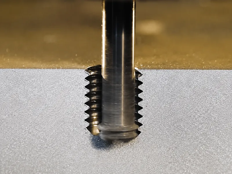
Threaded holes (tapped holes) are essential features in machined parts for connecting components with screws, bolts, or studs. A strong threaded hole requires more than just cutting internal threads – it depends on correct pilot drill size, adequate thread depth/engagement, robust material, sufficient wall thickness and edge distance, proper machining method, and thorough inspection. This guide explains what threaded and tapped holes are, compares drilling/tapping methods, and highlights design tips (drill size, depth, material, inserts, etc.) to maximize thread strength and reliability in CNC machined parts.
What Are Threaded Holes?
A threaded hole is a hole containing an internal helical thread cut or formed into the material. It allows a screw or bolt to fasten directly into the part. Threaded holes are extremely common in CNC machined parts, housings, brackets, fixtures, molds and assemblies, and can be formed in metals, plastics, or composites. In practice, threading may be done with cutting taps, thread milling, thread-forming taps, or by inserting a threaded bushing or coil. Regardless of method, the result is an internal screw thread ready to accept a fastener.
Tapped Holes vs Threaded Holes
Although often used interchangeably, “tapped hole” and “threaded hole” have distinct meanings. A threaded hole is any hole with threads (created by any method). A tapped hole specifically means the hole was threaded by a tap (a cutting tool). Other methods such as thread milling, forming, and inserts also produce threaded holes. In other words, every tapped hole is a threaded hole, but not every threaded hole is tapped. Thread milling and forming are alternatives when tapping is impractical.
| Feature | Tapped Hole | Threaded Hole | Main Difference |
|---|---|---|---|
| Created by | Cutting tap (hand or machine tap) | Any thread tool (tap, mill, insert) | Tapped = made by tap; threaded = general |
| Internal threads? | Yes | Yes | – |
| Tooling | Specific tap size/pitch needed | Can use thread mill (one tool for many sizes) | Tapped requires one tap per size |
| Typical use | Standard threads in steel, castings, etc. | Large/exotic threads, inserts, or many sizes | Thread milling flexible; tapping faster |
Common Types of Threaded Holes
- Through-threaded holes: The hole goes completely through the part. This makes tapping easier (no chip buildup at bottom) and allows easy inspection and assembly. Through holes are common in plates, brackets, flanges and general fixtures because the tap can exit the bottom.
- Blind threaded holes: The hole stops before the opposite face. This preserves the far side of the part for strength or sealing. Designing blind threads requires extra depth allowance for the drill point and tap lead (typically 2–3 full thread pitches extra). Blind holes trap chips at the bottom and limit tap travel, so they often need special taps (spiral-flute or bottoming taps) and careful chip evacuation.
- Counterbored threaded holes: A clearance counterbore (a larger diameter pocket) is added around the hole so the screw or bolt head (or a nut) can sit flush or below the surface. This is used when a flush exterior or room for a washer is needed in the final assembly.
- Threaded insert holes: These are holes drilled oversize to accept a threaded insert (e.g. Helicoil, E-Z Lok, or solid threaded insert). Inserts create durable threads in soft or thin materials. They are commonly used in aluminum or plastic parts, or for repair. After drilling the hole, an insert is installed to give a steel (or stronger) thread. See below for more on inserts.
Key Design Factors for Stronger Tapped Holes
Stronger threaded holes depend on several design factors:
- Material strength and hardness: High-strength materials (alloy steels, stainless steels) yield stronger internal threads than soft metals (aluminum, brass). Softer materials strip more easily.
- Thread size and form: Larger screw diameter spreads load over more material. Fine vs coarse pitch affects engagement and shear area.
- Thread engagement length: The length of mating threads in contact. Insufficient engagement leads to pull-out or stripped threads.
- Hole depth: Must accommodate full thread plus drill lead and clearance (especially for blind holes). Excessive depth adds machining time but little strength beyond the needed engagement.
- Wall thickness and edge distance: Thin walls or threads close to an edge can crack or tear out under load. Maintain sufficient surrounding metal (usually at least 1× bolt diameter to edge, 2× preferred).
- Thread type and class: Coarse threads (UNC/ISO) have more material removed but often better in thick parts; fine threads hold better in limited depth or thin walls. Thread tolerance (e.g. 2B/6H) affects fit and strength.
- Fastener material: Using stronger bolts (higher tensile) increases the clamp force and stress on the hole. The hole material must be able to handle it.
- Load direction and cycles: Threads under pure tension need strong engagement; threads carrying shear or repeated assembly may need inserts or harder material.
- Surface finish/coating: Smooth, clean threads have higher fatigue and torque capacity. Rough surfaces or coatings (zinc, anodize) affect final fit.
Note: Simply making the hole deeper does not necessarily make it stronger. Once basic engagement is met (typically 75–100% thread depth), extra depth mainly increases machining cost and tool wear. Instead, tailor depth/engagement to the material and loads.
Choose the Right Tap Drill Size
The drilled pilot hole diameter is critical. A common rule is: Tap drill ≈ (major diameter – pitch) (for metric) or ≈ major – (1/TPI) (for inch), which yields about 75% thread engagement. In practice, you should use a standard tap drill chart (ISO or ANSI). 75% engagement is considered a good balance: it provides roughly 95% of the theoretical thread strength while avoiding excessive torque.
- If the drill is too small, tapping torque rises sharply – a hole 0.1–0.2 mm undersize can increase torque by ~15–25%, risking tap breakage (especially in a blind hole or stainless steel). This can snap taps deep inside the part, requiring EDM removal or scrapping the part.
- If the drill is too large, the threads will be weak with less material to engage, making the joint prone to stripping or loosening.
Use standard charts such as ISO 261/965 or UNC/UNF tables based on ASME B1.1 unified screw threads to pick the drill size for 75% (or your target) engagement. In very hard materials (e.g. 300-series stainless, Inconel, titanium), many shops intentionally increase the tap-drill by +0.1–0.2 mm to reduce cutting torque (sacrificing only a few percent of thread strength for much higher tool life). Always verify drill size against standards rather than guess.
| Thread Size | Tap Drill (≈75% engagement) | Typical Use |
|---|---|---|
| M5 × 0.8 | 4.2 mm | Small aluminum panels |
| M6 × 1.0 | 5.0 mm | General mounting holes |
| M8 × 1.25 | 6.8 mm | Medium brackets, flanges |
| 1/4–20 UNC | #7 (≈0.201″) | Machinery screws |
| 3/8–16 UNC | 5/16″ (0.3125″) | Equipment mounts |
Values should be verified against the relevant thread standard, such as ISO 965-1 metric screw thread tolerances, ISO 261, and ANSI / ASME thread tables.
Thread Depth and Thread Engagement
Thread engagement is the length over which the external (bolt) and internal threads are in contact. Adequate engagement prevents stripping; too little can cause failure. In most steel assemblies, 1.0–1.5× the screw diameter of engagement is sufficient. For example, a steel or stainless bolt usually needs about 1–1.5D of full thread to achieve full strength. Softer materials need more: aluminum often requires ~2.0×D, and plastics even more (2.5×D or more) to avoid stripping.
However, “more is better” has diminishing returns. After roughly 75–100% engagement, additional depth adds little strength but increases machining cost. As Rapid Protos explains, 75% engagement already yields >95% of theoretical strength, while 100% depth only adds negligible strength at the cost of much higher tapping torque. Similarly, Tapmatic notes that beyond ~75% of full thread, torque rises sharply with little gain, and in very hard materials, even 50–65% engagement can be acceptable.
Design tip: Aim for at least the typical engagement for the material (see table below), but don’t overdo it. In blind holes, the total hole depth must exceed the thread engagement by a few pitches to allow for the tap’s lead or drill point. As a rule, provide extra depth (≥2–3 thread pitches) below the full thread callout.
| Material | Recommended Engagement Length |
|---|---|
| Steel (carbon/alloy) | ≈1.0–1.5× screw diameter |
| Stainless steel | ≈1.0–1.5× (works well due to strength) |
| Aluminum (6061, 7075) | ≈1.5–2.0× (softer alloy, needs more depth) |
| Brass/Copper | ≈1.5× (softer but strong threads) |
| Plastics (Nylon, POM, etc.) | 2.5× or more (weak base material) |
| Titanium (Ti-6Al-4V) | ≈2.0× (strong material, but gummy when tapping) |
Examples from design guidelines.
Material Selection for Threaded Holes
The workpiece material greatly affects tapped hole strength and machinability:
- Aluminum, including aluminum 6061-T6 and 6061-T651, is easy to drill and tap, but aluminum’s low shear strength means threads strip under load more easily. Use deeper engagement (see above) or threaded inserts in high-stress cases. Use sharp taps and ample lubrication to avoid galling or chip packing in blind holes.
- Steel (mild/1045, 4140, tool steel): Strong and holds threads well. Standard taps work easily. Hardened or tough alloy steels require slower speeds and more feed, and sometimes thread milling is preferable to avoid tap breakage in deep or blind holes.
- Stainless steel (e.g. 303, 304, 316L) is strong but work-hardens; tapping is more difficult, and thread galling can become a problem during assembly if lubrication or fastener selection is poor. Use appropriate cuts (spiral-flute taps), heavy-duty cutting fluid, and sometimes larger tap drills (65–70% engagement) to reduce torque. Thread milling or forming taps are often used in stainless or difficult alloys to improve tool life.
- Brass/Bronze: Soft and easy to machine. Threads are strong due to metal’s ductility; standard tap drills (≈75% engagement) work fine. Excellent for inserts or bearing surfaces.
- Titanium: Very strong but gummy and low thermal conductivity. Drilling and tapping titanium requires slow feeds, high lubrication, and CBN or HSS-E tap tools. Small threads in titanium can be difficult; thread milling is often used. Engagement similar to steel (~2.0×) for strength.
- Plastics (Nylon, Delrin, POM): Very low strength. Use special thread forms or inserts (e.g. molded or heat-set inserts) to avoid thread stripping. If tapped, use 2–3× engagement and coarse threads.
In summary, aluminum and plastics benefit most from inserts or extra depth, steels generally form strong threads, and exotic materials (titanium, Inconel) may require thread milling or special taps.
Blind Holes vs Through Holes: Design Considerations
Through-holes and blind holes behave quite differently:
- Through holes are easier and cheaper to tap. They allow the tap to pass out the other side, so chips escape freely and no special bottom clearance is needed. Through holes are easier to inspect and let coolant and debris flow out. In batch parts with many threads, through holes speed up production.
- Blind holes are more challenging. They trap chips at the bottom and limit how deep the tap can go before bottoming out. Blind threads require extra pilot-hole depth for the drill’s point and the tap’s lead chamfer. If this clearance is insufficient, taps will overload and break. Often a bottoming tap or spiral-flute tap is used for the final few threads. Designers should avoid specifying full-length thread to the bottom of a blind hole unless necessary; leaving 2–3 pitch lengths of extra hole depth below the full-thread callout is good practice.
- Inspection and failure: In a blind hole, a broken tap has no escape; extraction is difficult and usually ruins the part. By contrast, in a through hole a broken piece can fall out. Use extra caution (tapping fluid, peck tapping) in blind threads.
| Feature | Blind Threaded Hole | Through Threaded Hole | Design Note |
|---|---|---|---|
| Chip evacuation | Poor (chips accumulate at bottom) | Easy (chips exit freely) | Spiral taps or pecking needed for blind holes |
| Drill depth requirement | Must exceed thread depth by 2–3 pitches | Just meets thread depth | Provide extra depth for drill point clearance |
| Tap type | Often requires bottom or spiral-tap | Standard plug tap can be used | Bottom tap needed to cut final threads |
| Inspection | Harder to measure actual depth/fit | Easier (full thread accessible) | May need a probe or gauge with depth notch |
| Risk of tap breakage | Higher (no exit, chips jam) | Lower (broken tap can exit) | Extra care (lubricant, pecking) for blind holes |
(Sources: UNeed PM, RivCut)
Wall Thickness and Edge Distance
The strength of a tapped hole also depends on the surrounding material:
- Wall thickness: Tapping too close to a thin edge can crack or pull the part under load. As a rule-of-thumb, maintain at least 1× the screw diameter of material thickness from the hole center to any free edge. Thicker is better (2× or more when possible). For example, RivCut notes that a ¼–20 screw (0.25″ diameter) needs about 0.25″ of wall; less than that will likely crack. Very thin walls (e.g. <1×D) should generally be avoided or reinforced (e.g. use a sleeve or switch to a smaller screw).
- Edge distance: The center of the hole should also be kept a safe distance from the part edge. In steel, codes typically require ≥1× the bolt diameter. In aluminum, minimum is 1.5× per the Aluminum Design Manual (and 2× or more is recommended for full strength). If the edge distance is too small, the metal can tear or deform under bolt preload.
In summary, ensure enough metal around a tapped hole to avoid tearing: typically ≥1–2× bolt diameter from center to edge, and wall thickness ≥1× diameter. Reinforce or move holes that violate these limits.
Threaded Inserts for Stronger or Repairable Threads
Threaded inserts (such as Helicoils, E-Z LOKs, Keenserts, etc.) are a powerful way to improve thread strength, especially in soft or weak materials:
- Increased strength: Inserts distribute the load over a larger bearing area and use the insert’s harder material for the threads. This makes the connection much stronger. For example, a steel insert in aluminum can have 2–3× the thread engagement strength of a direct tapped thread. The insert provides a durable, wear-resistant thread even if the base metal is weak.
- Wear and endurance: Inserts resist thread wear and galling better than soft base metal. They allow many cycles of assembly/disassembly without stripping. As Qewit explains, inserts “provide a tough thread layer that wears slower and stays good after many tightening cycles”, ideal for service panels or maintenance-heavy parts.
- Repairability: If threads become damaged, an insert can often be installed to restore function without scrapping the entire part. As Bossard notes, inserts “allow you to replace defective threads quickly and cost-effectively”. This makes inserts useful in prototypes or field-repairable assemblies.
Inserts add cost (typically $1–$3 each plus installation labor) but greatly reduce the risk of thread failure. Use inserts when mating material is soft (aluminum, magnesium, plastic), for safety-critical joints, for very high-cycle use, or whenever thread longevity is paramount.
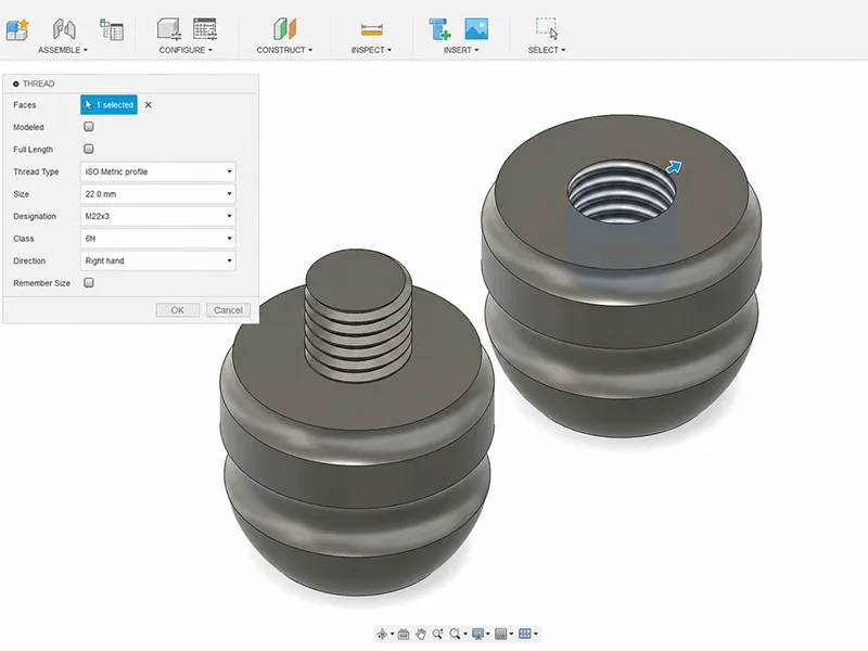
How Threaded Holes Are Made in CNC Machining
Threaded holes in CNC parts are most commonly created by one of these methods:
- Tapping: A cutting tap is plunged into the pre-drilled hole. This is the fastest and most common method for standard threads in through-holes or shallow blind holes. Standard taps include plug taps (for through holes), bottoming taps (for blind holes), spiral-point taps (drive chips forward in through holes), and spiral-flute taps (pull chips out of blind holes). Tapping cuts the entire thread in one operation, making it very efficient. Its limitations are that each size requires its own tap, and taps can break if the hole is too deep, undersized, or poorly aligned. Good lubrication and rigid tapping (synchronized machine tapping) are important to reduce tap breakage and ensure accuracy.
- Thread milling: A thread mill is a rotating cutter that moves in a helical path to cut the thread profile. It requires a pre-drilled hole. Thread milling is slower per hole than tapping, but far more flexible: one thread-mill tool can cut many thread sizes (same pitch), and it works equally well in through or deep blind holes. It also handles tough materials and large diameters without risk of breakage. Thread milling is preferred for large threads, exotic materials (Inconel, titanium), or when the hole is blind or near an edge. CNC mills synchronize X–Y motion to cut each thread turn, allowing very controlled depth.
- Thread forming (roll tapping): This method uses fluteless taps to plastically form threads by displacing material instead of cutting. Forming taps (cold-roll taps) leave no chips and work-harden the thread flanks, producing stronger and smoother threads. The workpiece material must be ductile and the hole drilled slightly oversize. Form taps offer longer tool life and low risk of breakage, making them excellent for high-volume runs in aluminum or mild steel. However, they cannot be used in hard or brittle materials.
- Threaded inserts: As described above, inserts are installed into a drilled and often counterbored hole to provide threads. In CNC parts, the hole for an insert is usually tapped oversize (to the insert’s outer diameter), then the insert (coil or solid) is screwed or pressed in. The install tool cuts internal lock threads in the insert, fixing it in place.
Common Problems When Making Threaded Holes
Some frequent issues in manufacturing and design of threaded holes include:
- Stripped threads: Often caused by inadequate thread engagement (too shallow), undersized base material (soft metal), or using an oversized drill. Prevent by using proper engagement length, correct drill size, or inserts in soft parts.
- Broken taps: Caused by a too-small pilot hole, too much depth, lack of lubrication, or misalignment. A small error (0.1–0.2 mm undersize) can surge tapping torque by 15–25%. Prevent by verifying drill size, using spiral or peck-tapping in deep holes, and supporting the tap properly. Always check that hole is long enough for the drill point and tap chamfer.
- Oversized holes: Drill wander or wrong size drill results in weak, oversize threads that won’t hold. Always confirm drill size with actual measurements or drill gauge, and consider drill pilot guidance for precision.
- Misaligned threads: Caused by part or tool mis-fixturing. Ensure the hole axis is square to the machined face (especially critical in blind holes). Use rigid fixturing and correct centers or stops.
- Burrs and chatter: Tapping can leave burrs at the hole exit. Add a chamfer on the hole entry (e.g. 0.3–0.5 mm at 45°) to guide the tap and capture chips. Remove burrs afterwards to ensure flush fit of fasteners.
- Poor chip evacuation: Especially in blind holes, chips can clog and cause tap breakage or poor thread form. Use spiral taps or “peck tapping” (periodic reversing) to break and remove chips, or use compressed air if possible.
- Thread galling: In stainless steel or aluminum, galling can occur (fastener seizing). Use lubrication or specify anti-galling coatings/fasteners. Inserts also prevent galling of the base material threads.
Table: Common Threaded Hole Problems
| Problem | Cause | Solution |
|---|---|---|
| Stripped threads | Shallow engagement, soft metal, oversized hole | Increase engagement (depth or inserts), correct drill size |
| Broken taps | Pilot hole too small, deep tapping, dry cutting | Use correct drill size, step tapping, use lubricant, thread mill for hard holes |
| Oversize hole | Drill drift, wrong tool | Verify drill bit, use spotting drill or guidance bushing |
| Misaligned threads | Poor fixturing or perpendicularity | Rigid clamps, use multiple locating points, verify setup |
| Burrs on exit | No chamfer, dull tap | Chamfer hole entry (0.3–0.5 mm at 45°), deburr after tapping |
| Chip clogging | Blind hole, wrong tap type | Use spiral-flute taps, shorter flute, peck-drilling, clearing operations |
| Galling threads | Stainless/aluminum without lube | Use lubricant or anti-galling bolt finish, or use inserts |
How to Improve Threaded Hole Strength
To maximize tapped hole robustness in your design and process, consider these tips:
- Use the correct drill size: Always drill to the size specified for about 75% engagement (see chart above). Verify drill calibration and consider +0.1–0.2 mm extra for very hard materials to save tap life.
- Specify adequate engagement: Follow the engagement rules (see table above). Don’t under-cut thread depth “to save depth” in aluminum or soft materials; bolts strip out of aluminum mostly due to shallow threads.
- Maintain material around the hole: Keep at least 1× diameter of wall thickness and edge distance (2× better). Avoid threads right at an edge or on thin flanges unless reinforced.
- Consider inserts for soft or critical holes: In aluminum, plastic, or high-cycle joints, inserts greatly improve durability. Plan insert type and hole size in the design stage.
- Choose the right fastener size and thread class: Using a slightly larger screw with the same hole often increases strength. For high loads, consider a higher-strength bolt (e.g. Grade 8 or 10.9) and matching internal thread spec (2B/6H).
- Chamfer the hole entry: A small chamfer (0.3–0.5 mm, 45°) at the hole entrance guides the tap and prevents cross-threading or damage.
- Use proper lubricant: Always use cutting fluid or tapping oil when creating threads, especially in steel or stainless. Lack of lubrication causes metal-to-metal contact, heat, and tap breakage.
- Use thread milling or form taps when needed: For very large threads (>½″), very hard materials, or when absolute reliability is required, consider thread milling (eliminates breakage risk) or forming taps (stronger threads with no chips).
- Peck tapping for blind holes: In deep blind holes, intermittently retract the tap to clear chips. This reduces stress.
- Design for inspection: Specify full thread depth (minimum) on drawings, and clearly indicate if a bottom tap is needed. Provide tolerances or callouts for depth.
Incorporating these practices during the DFM review ensures threaded holes can be made robustly and cost-effectively.
Threaded Hole Inspection and Quality Control
Thread quality directly affects assembly reliability, so CNC quality control is important for parts with tapped holes, inserts, or fit-critical internal threads. Common inspection methods include:
- Thread plug gauges (GO/NO-GO): This is the simplest check. Thread gages are used to inspect mating threaded parts and verify functional thread fit. A GO thread gauge (with proper class of fit) must screw in fully to the full thread depth without force. A NO-GO gauge should not fit more than 1–2 turns. This verifies that the internal thread meets the minimum and maximum size.
- Plug gauges with depth notches: For blind holes, go/no-go gauges with built-in depth notches (as per ASME B89.1.5) allow checking that the thread is deep enough. The go gauge’s notches indicate minimum and maximum depth tolerance.
- CMM or vision measurement: Coordinate Measuring Machines can check hole position, straightness, and even sample-thread form if equipped with special probes. CMMs ensure the hole is in the correct location and orientation, per drawing datums. (CMMs can measure actual thread profile in some cases.)
- Fastener fit test: A practical test is simply screwing in the intended bolt/screw to confirm it seats correctly and isn’t loose or too tight.
- Burr and finish check: Visually inspect for burrs or surface defects. The mating bolt should engage smoothly. Deburr chamfers after tapping.
- Material and treatment verification: For critical parts, verify the material grade and any heat treatment (hardness) to ensure it meets spec.
Combining these QC steps helps catch any tapping errors early. For example, a GO/NO-GO gauge immediately spots an undersize or oversize thread, and a quick fit check ensures assembly will work without surprise.
Cost Considerations for Threaded Holes
Several factors affect the manufacturing cost of threaded holes:
- Quantity: High volumes lower unit cost (setup and tap cost spread out). Prototyping or one-offs cost more per hole.
- Hole size and depth: Larger diameter and deeper holes take more time. Very deep threads (e.g. >2–3×D) add tapping time. RivCut notes that increasing from 2× to 3× depth adds ≈15% more tapping time.
- Blind vs. through: Blind holes cost more because they often require a second bottom-tapping pass. RivCut estimates 30–50% extra cost per hole for bottom-tapped blind holes versus through holes.
- Material: Tough materials (stainless, titanium, hardened steel) slow the process and wear out taps, increasing tool costs and cycle time.
- Tap tool cost: Non-standard thread sizes or forms need special taps (can cost $50–$200 each). Using standard UNC/ISO threads avoids this.
- Thread inserts: Each insert adds material and labor cost (often $1–$3 per hole). But this cost may be offset by savings from avoiding repairs or part failures.
- Inspection and rework: Tighter tolerances or critical features may require more inspection time (CMM, gauges). Fixing stripped threads or broken taps (via rework or scrap) also adds cost.
- Production setup: Multiple different thread sizes on one part mean more tap/tool changes, increasing cycle time and potential for error.
Unnecessary over-specification drives up cost. For example, calling for 100% thread depth where 75% is sufficient will only slow the job. As a designer, balance functional needs against cost: use adequate but not excessive thread length, standard sizes, and specify through-holes when possible.
Conclusion
Creating a strong threaded hole in CNC parts involves careful attention to every detail of the design and process. A robust tapped hole starts with the correct hole size (tap drill) and material choice, and continues through proper thread depth, engagement, and machining method. Coarse threads (UNC/ISO) and taps work well for most applications, but thread milling, forming taps, or inserts may be better for large, hard, or soft-material applications. Always maintain sufficient wall thickness and edge distance, use chamfers and lubrication, and inspect with go/no-go gauges. By following sound guidelines (e.g. ~75% engagement for ~95% strength, ≥1×D wall thickness, and full callouts for depth on drawings), you can avoid stripped threads, broken taps, and costly rework. In short, stronger threaded holes are achieved by matching the hole design to the loads, material, and assembly requirements, not simply by going deeper. Well-designed taps in proper materials and thorough quality checks ensure reliable, high-strength threaded connections without unnecessary machining cost.
FAQs About Making Threaded Holes
What is the best way to make threaded holes?
For most standard applications, tapping (using a cutting tap) is fast and efficient. However, in special cases you might choose alternatives: use thread milling for large-diameter, deep, or hard-material holes (it’s slower but avoids broken taps), use thread forming taps in ductile materials for very strong threads without chips, or use inserts in soft materials to get durable threads. The right method depends on material, size, and performance needs.
How deep should a tapped hole be?
Thread depth depends on screw diameter, material strength, and load. A common guideline is at least 1× to 1.5× the screw diameter of thread engagement for steel, more for softer materials. For example, a 10 mm screw in aluminum might need ~20 mm of threads, while the same in steel might be ~15 mm. For blind holes, always drill a couple of thread pitches deeper than the tapped depth to clear the tap point. Do not overshoot depth beyond what the functional load requires, as this only wastes time.
Why do tapped holes strip?
Stripping usually happens when there isn’t enough thread engagement or the base material can’t handle the load. Common causes include: using too shallow a thread (especially in soft materials like 6061 aluminum), drilling the hole too large (weak threads), over-tightening the bolt, or using an incorrect fastener grade. To prevent stripping, ensure proper drill size, adequate engagement, use inserts in soft metals, and choose an appropriate bolt/hole class.
Are threaded inserts stronger than tapped holes?
Yes, in many cases. Threaded inserts (steel coils, etc.) make the hole effectively stronger by using the insert’s harder material for the threads. They distribute load over more area and resist wear, so inserts often yield 2–3× greater thread strength in soft materials. Inserts also allow repeated assembly without wear, which a direct tap in aluminum would not sustain. Inserts do add cost per hole, but they greatly increase durability and are recommended for high-cycle or load-critical joints.
What is the difference between tapping and thread milling?
Tapping uses a multi-flute tap to cut the full thread profile in one go. It’s fast and great for straight, accessible holes. Thread milling uses a single-point or multi-edge milling cutter that spirals down the hole to cut the threads. Milling is slower but offers more flexibility: one tool can cut many sizes of the same pitch, it can handle deep blind holes and tough materials without snapping, and it can precisely control fit. Tapping is best for common, smaller threads in standard materials; thread milling is preferred for large diameters (>½″), hard or exotic materials, or when a risk of tap breakage is unacceptable.
How are threaded holes inspected?
The simplest check is a go/no-go thread plug gauge. The GO plug gauge (to the specified class of fit) should screw into the hole freely to the full depth. The NO-GO gauge should not enter beyond a few turns. If the NO-GO can be screwed in, the thread is oversized (or the gauge is wrong). In blind holes, depth notches on a go gauge can verify minimum depth. For critical parts, coordinate measuring machines (CMMs) or vision systems can measure hole position and alignment. Also perform a fit test with the actual fastener to ensure the bolt threads in smoothly (no binding, cross-threading, or looseness). Checking for burrs and verifying any surface coating or hardening is also part of quality control.

