
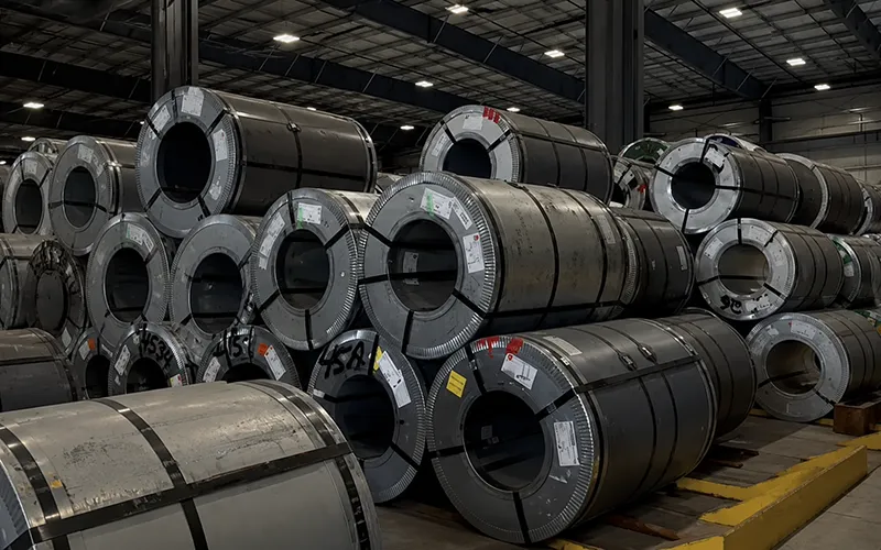
In rapid prototype development, understanding Sheet Metal Material Types helps explain why sheet metal has long remained a mainstream choice not simply because it is “cheap,” but because it can achieve a practical balance among strength, manufacturability, lead time, and surface appearance. For products such as electronic enclosures, mounting brackets, panels, covers, cabinets, and structural parts, the performance differences among aluminum, stainless steel, carbon steel, galvanized steel, copper, brass, and titanium directly affect whether the first round of prototyping goes smoothly, including whether bending will crack, whether welding will cause deformation, whether the surface is corrosion-resistant, whether the weight exceeds the target, and whether normal assembly can still be achieved after powder coating, anodizing, or passivation. In actual prototyping, correct material selection is often more important than simply pursuing high strength, because rapid prototyping emphasizes stock availability, ease of processing, and the ability to quickly verify functions. This guide explains common sheet metal materials, key properties, the relationship between thickness and process compatibility, and how to make more reliable prototype decisions between cost and performance according to engineering selection logic.
What Is Sheet Metal
Sheet metal materials usually refer to thin, flat metal product forms. Common processing methods include laser cutting, stamping/punching, bending and forming, welding, riveting, and subsequent finishing.Compared with plate, sheet metal is usually thinner and has stronger formability, making it more suitable for enclosures, brackets, panels, and boxes that require “cutting first, then bending, then assembling.” However, a strict thickness boundary is not completely unified across the whole industry, and different suppliers and material systems may use different habits. Many service providers and steel mills also clearly recommend that drawings should mark the actual thickness in mm/in instead of only writing gauge.
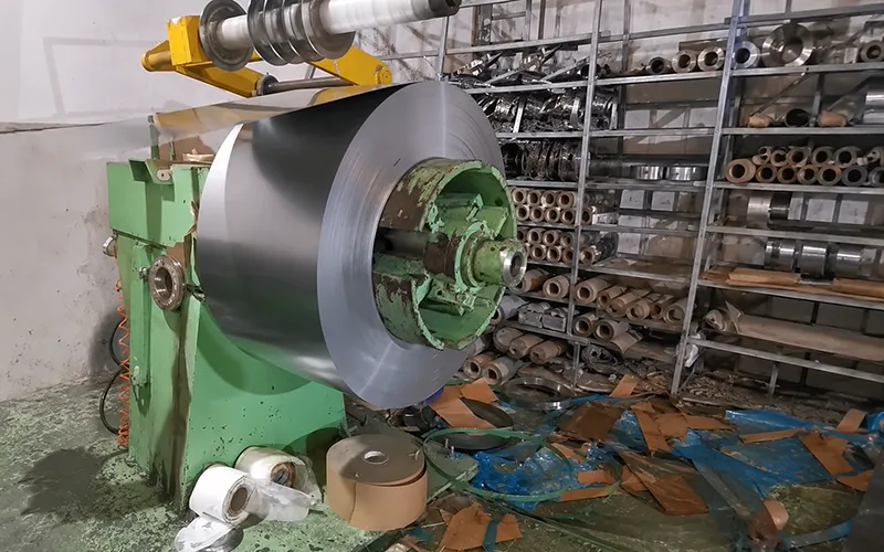
From the perspective of supply forms, what is common in engineering is not only single flat sheets, but also sheet, coil, strip, blank, perforated sheet, and pre-finished sheet. Coil slitting, cut-to-length shearing, and pre-coated slitting, cut-to-length shearing, and pre-coated supply are all common ways to shorten lead time and reduce secondary processing costs.
Why Sheet Metal Is Commonly Used in Rapid Prototyping
From engineering prototyping experience, the biggest advantage of sheet metal is not that it is “universal,” but that it is especially friendly to low-volume, fast-iteration, functional verification, and controllable sheet metal cost. Digital sheet metal manufacturing can usually complete cutting, bending, assembly, and surface treatment within a few days. Compared with dedicated large stamping dies, the prototype stage relies more on lasers, CNC punching machines, and bending tooling, with lower upfront dedicated tooling investment and easier absorption of design changes. For product development teams, this means you can first validate the structure, assembly, heat dissipation, and appearance samples before deciding whether to move toward a mass-production tooling route.
Sheet metal also has a good strength-to-weight ratio and engineering scalability. Based on the capabilities publicly shown by digital manufacturing service providers, sheet metal supports both the prototype stage and low-volume and bridge production. Common applications cover electrical enclosures, chassis, brackets, covers, panels, cabinets, mounting parts, and multi-part welded/riveted assemblies. For consumer electronics, industrial equipment, medical, automotive, and aerospace prototypes, sheet metal is often more economical than hollowing out an entire block by CNC and closer to real use conditions than pure plastic prototypes.
Common Sheet Metal Material Types
The following section explains the most common material systems in rapid prototyping. When selecting materials, do not only look at nominal strength. You also need to consider temper/condition, formability, corrosion resistance, welding method, stock thickness, and surface treatment compatibility.
Aluminum Sheet
Aluminum sheet is one of the most common sheet metal materials in rapid prototyping. The core reasons are light weight, corrosion resistance, good thermal conductivity, and high cutting and machining efficiency. The Aluminum Association’s aluminum overview also highlights aluminum’s lightweight versatility, corrosion resistance, recyclability, and broad industrial use. In workshop prototyping, if a customer wants to make an enclosure, lightweight bracket, heat-dissipating housing, or non-heavy-load panel, aluminum is often the first choice. In particular, 5052, 3003, and 6061 almost cover most prototype needs.
Among them, 5052 uses magnesium as the main alloying element, with good formability and good weldability, making it suitable for bent parts. 3003 is mainly manganese-based, with moderate strength but very friendly formability, suitable for deep drawing, rolling, and general enclosure parts. 6061 can be heat treated to higher strength and has good mechanical properties and weldability, but outside the soft temper, its bending friendliness is usually not as good as 5052. A common practice in prototyping is to prioritize 5052 when large deformation is required, and to consider 6061 when higher stiffness or later machined reference surfaces are needed.
Typical applications include electronic equipment housings, lightweight brackets, automotive prototype parts, aerospace panels, and heat dissipation components. Especially when a prototype needs to balance weight and heat dissipation, aluminum has very high overall cost-effectiveness.
Stainless Steel Sheet
The advantages of stainless steel sheet are corrosion resistance, durability, and good surface stability. 304 is the most common general-purpose austenitic stainless steel, suitable for food, medical, industrial, and architectural environments. 316/316L contains molybdenum, so it usually has more advantages than 304 in chloride and more demanding corrosive environments. The low-carbon version 316L is also more helpful in controlling the risk of intergranular corrosion in thicker welded parts.
From a prototyping perspective, stainless steel is commonly used in medical device housings, industrial protective covers, outdoor panels, food equipment parts, and corrosion-resistant brackets. But engineering also needs to accept its cost: compared with aluminum, stainless steel is usually harder to cut and bend, has more obvious springback, and has a narrower bending process window. Therefore, if a prototype has many bends, tight radii, close hole spacing, or cosmetic surface requirements, an early DFM review must be done before production.
Carbon Steel Sheet
The core advantages of carbon steel sheet are a high strength-to-cost ratio, convenient welding, and broad procurement coverage. The most common materials in prototype projects are cold-rolled low-carbon steel and hot-rolled steel. Cold-rolled steel usually has a flatter surface, tighter dimensional control, and higher strength and hardness. Hot-rolled steel is more suitable for scenarios where the surface requirement is not high but structural strength and cost matter more.
In actual prototype development, cold-rolled steel is more commonly used for enclosures, panels, brackets, fixtures, and industrial parts that require painting. Hot-rolled steel is more suitable for non-appearance-critical frames, bases, or rougher industrial protective parts. The problem with carbon steel is also clear: bare material is easy to rust. If the prototype needs outdoor testing, salt spray testing, or long-term assembly verification, powder coating, painting, plating, or switching to stainless steel/galvanized steel usually needs to be considered at the same time.
Galvanized Steel Sheet
Galvanized steel is essentially steel sheet with a zinc coating on the surface, aiming to improve corrosion resistance while maintaining the basic strength of steel. Nucor clearly states that galvanized steel obtains better corrosion resistance and durability by applying a zinc layer to the surface of cold-rolled or hot-rolled substrate. For rapid prototypes, it is very suitable for HVAC parts, outdoor enclosures, general industrial covers, and cost-controlled rust-resistant structural parts.
However, galvanized steel is not a “blindly better” material. First, the edges after cutting and bending expose the base material. Second, the effect of the coating must be considered during welding and subsequent processing. Many service providers also remind customers that after laser cutting pre-coated steel, the coating around holes and contour edges will be locally removed. Therefore, if the prototype is exposed to highly corrosive environments for a long time, edge protection still needs to be evaluated separately.
Copper Sheet and Brass Sheet
If the prototype focuses not on structure but on electrical conductivity, thermal conductivity, shielding, or appearance, copper and brass become candidates. CDA materials point out that copper and its alloys are excellent electrical and thermal conductors, and when the design goal is high electrical/thermal conductivity, copper and high-copper alloys have higher priority.
Copper sheet is suitable for electrical contact parts, conductive connection strips, heat spreaders, and EMI shielding parts. Brass, while maintaining a certain level of conductivity, has better decorative appearance and good cold workability. The official database gives C260 brass an Excellent cold workability rating, making it attractive for custom hardware, nameplates, decorative panels, and small formed parts. The disadvantages are also realistic: material cost is usually higher than carbon steel and often higher than common aluminum sheet.
Titanium Sheet
Titanium sheet is usually not the “default option” for rapid prototyping, but in high-performance lightweight, corrosion-resistant, medical, or aerospace projects, it is a very strong alternative. ATI and Titanium Industries materials both emphasize titanium’s high strength-to-weight ratio, corrosion resistance, and its applications in aerospace, medical, marine, and industrial fields.
What really needs attention in prototyping is that titanium is expensive, difficult to form, and has higher springback and processing difficulty than aluminum and ordinary steel. If it is only for an appearance prototype or general assembly verification, titanium is usually not the most cost-effective solution. But if the project requires real high-strength lightweight verification or chemical corrosion resistance verification, the value of titanium becomes very clear.
Common Sheet Metal Material Comparison Table
| Sheet Metal Material | Main Advantages | Main Limitations | Common Prototype Uses | Basis |
|---|---|---|---|---|
| Aluminum sheet | Light, corrosion-resistant, good thermal conductivity, easy to process | Bending performance is average in some high-strength tempers | Enclosures, panels, lightweight brackets, heat dissipation parts | Official data for 5052/3003/6061 |
| Stainless steel sheet | Corrosion-resistant, durable, stable surface | Bending and cutting are more difficult than aluminum, with more obvious springback | Medical housings, industrial covers, outdoor panels | Official materials for 304/316 |
| Carbon steel sheet | High strength, low cost, easy to weld | Requires anti-rust coating | Brackets, fixtures, frames, industrial covers | Official data for cold-rolled/hot-rolled steel |
| Galvanized steel sheet | More corrosion-resistant than bare steel, good surface consistency | Coating effects at cut edges/weld zones need consideration | HVAC, outdoor boxes, general industrial panels | Official galvanized steel materials |
| Copper sheet / brass sheet | Good electrical and thermal conductivity; brass has good appearance and cold workability | Higher cost | Conductive strips, heat spreaders, shielding parts, decorative hardware | CDA official materials |
| Titanium sheet | High strength-to-weight ratio, strong corrosion resistance | Expensive, difficult to form and process | Aerospace brackets, medical and high-performance lightweight parts | ATI/TI official materials |
Key Properties That Must Be Compared Before Choosing Sheet Metal
When selecting materials in engineering, I usually first look at six core questions: whether it is strong enough, whether it is too heavy, whether it can be bent, whether it will rust, whether it is easy to weld, and whether the lead time is stable. This is closer to real projects than looking at only one mechanical parameter. For rapid prototypes, the “best” material is never the strongest or the cheapest, but whether it matches the prototype’s function, environment, forming method, and testing goal. The supplier’s stock thickness, surface treatment chain, and DFM risks are often just as important as the material properties themselves.
Key Property Comparison Table
| Property | Why It Matters | Common Better Material Examples | Basis |
|---|---|---|---|
| Strength / stiffness | Determines whether load-bearing, anti-deformation, and structural verification are effective | Carbon steel, 6061, titanium | |
| Weight | Determines portability, overall product weight, and lightweight verification | Aluminum, titanium | |
| Corrosion resistance | Determines service life in outdoor, humid, and chemical environments | 316, aluminum, titanium, galvanized steel | |
| Bendability | Determines whether the first prototype will crack and whether springback is controllable | 3003, 5052, C260 brass | |
| Weldability | Affects structural part welding, box sealing, and deformation risk | 5052, 6061, low-carbon steel, 316L | |
| Thermal conductivity | Affects heat sinks, heat-spreading housings, and thermal testing | Copper, aluminum | |
| Electrical conductivity | Affects conductive parts, grounding strips, shielding, and busbar prototypes | Copper, high-copper alloys | |
| Surface treatment compatibility | Affects corrosion resistance, appearance, insulation, and brand presentation | Aluminum is suitable for anodizing; steel parts are suitable for powder coating/plating; stainless steel is suitable for passivation/polishing | |
| Availability / lead time | Directly affects when the prototype can ship | Common stock materials such as 5052, 6061, 304, 316, CR 1008, galvanized steel | |
| Total cost | Includes material, cutting, bending, welding, finishing, and rework | Low-carbon steel and common aluminum materials are usually more friendly |
How to Choose Sheet Thickness and Gauge
Sheet thickness has a very direct impact on rapid prototypes: it not only determines strength and stiffness, but also affects weight, minimum bend radius, processing force, vibration performance, cost, and lead time. Thin material is easier to bend, but it is more prone to bulging, deformation, or vibration. Thick material is more stable, but the bend radius must be enlarged, press capacity requirements are higher, and processing cost is usually higher.
Many engineering drawings still habitually write gauge, but when actual prototyping is carried out, the actual thickness must be clearly written. This is because the same gauge does not have the same actual thickness in different material systems, and steel mills and service providers are increasingly inclined to supply based on decimal thickness/actual thickness. Nucor clearly states that they do not provide a gauge chart as the main specification basis, but focus more on nominal or minimum decimal thickness to obtain more precise manufacturing control.
From a DFM perspective, sheet thickness selection must at least check these factors at the same time: load requirements, bend radius, part size, hole diameter and hole-to-edge distance, rivet nut/press-fit fastener specifications, welding heat input, surface treatment thickness, and the prototype’s real testing conditions. Based on experience, the most common reason for first-round prototype failure is not “insufficient material strength,” but mismatch between thickness and bend radius, holes being too small or too close to the edge and bend line, and fit tolerances being consumed after finishing.
Common Sheet Metal Manufacturing Processes for Rapid Prototypes
Prototype sheet metal is usually not completed by a single process, but by a combined route of “cutting + bending + assembly + surface treatment + CNC machining when necessary.” The process itself will in turn constrain material selection, so material selection and process determination must be done together.
Laser Cutting
Laser cutting is suitable for flat contours, holes, and complex shapes. Its characteristics are high precision, fast speed, and high contour freedom. TRUMPF materials mention that laser cutting is non-contact processing, suitable for very fine contours, and the kerf can be relatively small. But it is still thermal cutting after all. When the material and thickness are not suitable, heat-affected-related problems may appear at the edge.
Waterjet Cutting
The biggest advantage of waterjet cutting is that there is no heat-affected zone. OMAX clearly states that waterjet cutting can cut many materials without changing material properties, making it suitable for thick plate, heat-sensitive materials, and scenarios where heat effects are not desired. It is also often used to create near-net-shape blanks before subsequent machining.
In terms of edge quality, waterjet cutting is not fixed. OMAX’s quality level explanation points out that the slower the cutting speed, the higher the edge quality; conversely, the faster the speed, the rougher the edge surface. This is also why, if the prototype drawing is very sensitive to edge appearance and subsequent assembly surfaces, it is best to clearly state the edge quality during the quotation stage.
CNC Punching
CNC punching machines are especially suitable for repeated hole patterns, louvers, shallow drawing, slots, ventilation arrays, and panel parts. Materials from Protolabs and OEM sheet metal factories all point out that punching is suitable for quickly forming holes, slots, and regular features in the flat sheet state, and it is very efficient for chassis panels, cabinet panels, and control panels.
But engineering must understand its limitations: punching relies on tool libraries. The more repeated standardized features there are, the higher the efficiency. When the shape is too free-form or the contour keeps changing, laser cutting is usually more flexible.
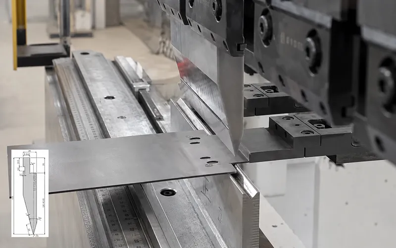
Bending and Press Brake Forming
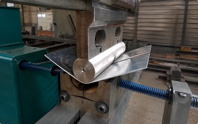
Bending determines whether an enclosure or bracket can become a real three-dimensional part from a two-dimensional blank. Press brakes are suitable for making flanges, U-shaped parts, L-shaped brackets, box side walls, and channel parts. For prototypes, inside radius, material elongation, springback, and grain direction are the most critical variables.
From DFM rules, many first-round prototype scrap issues can be traced back to bending design errors. For example, if features are too close to the bend line, there is usually a risk of deformation within about 4 times the sheet thickness from the bend line. The minimum flange length is also often required to be at least about 4 times the sheet thickness. Insufficient hole/slot size and edge distance can easily cause material deformation.
Welding and Assembly
Frames, boxes, covers, and multi-sheet structural prototypes often require welding, riveting, or press-fit fastener assembly. The most important thing to control in advance here is heat input and deformation. Lincoln Electric clearly points out that higher welding heat input usually brings greater deformation. This is especially obvious on thin sheet box parts: if weld layout and fixtures are not considered enough, both the prototype appearance and dimensions may be pulled out of shape.
CNC Finishing After Forming
When a prototype has critical hole positions, countersinks, local mating surfaces, or post-weld datum requirements, CNC finishing after sheet metal forming is a very common route. Many service providers classify this type of capability as “critical-to-quality features” or CNC-machined features, used to improve final accuracy after bending/welding.
Common Surface Treatments for Sheet Metal Prototypes
Surface treatment is not only to “make it look good,” but more importantly to improve corrosion resistance, wear resistance, insulation, cleanability, and brand presentation. And the more rapid the prototype is, the earlier surface treatment should be included in the design review, because it changes thickness, affects fit, masks conductive surfaces, and may even change prototype test results. Protolabs also clearly reminds that surface treatment increases part thickness and may affect functional areas, threaded holes, and assembly relationships.
For aluminum parts, the most common treatment is anodizing. Aluminum anodizing converts the surface into a durable, corrosion-resistant oxide layer, suitable for both appearance and corrosion resistance needs. At the same time, the anodic film itself has electrical insulation properties, which is sometimes an advantage for electronic prototypes and sometimes requires grounding surfaces to be avoided.
For steel parts and many conductive metals, powder coating is a very common type of treatment in prototyping. The powder coating layer is usually thicker and more scratch-resistant than ordinary wet paint, and it is also more helpful for appearance consistency. But it affects holes, threads, and tight mating surfaces, so masking areas should be clearly defined at the design stage.
For stainless steel, passivation is the most common functional post-treatment. The definition in ASTM A967 states that the essence of passivation is to accelerate the formation of a passive film on the surface of clean stainless steel through chemical treatment. In industrial practice, it is also usually understood as removing free iron and promoting the formation of a dense oxide protective layer.
In addition, these surface methods are also commonly used in engineering:
Brushing: Forms a uniform directional texture, suitable for appearance parts and end-user visible surfaces.
Polishing: Improves reflectivity, cleanability, and corrosion resistance in some environments.
Bead blasting: Forms a uniform matte or satin texture, and is also commonly used as a pretreatment before anodizing or painting.
Plating: Such as nickel, zinc, tin, etc., used for corrosion resistance, wear resistance, or conductivity.
Black oxide: Has a good black appearance, but corrosion resistance is weak when used alone, so it usually needs post-oiling/waxing.
Hot-dip galvanizing: Relies on zinc layer barrier protection + sacrificial anode protection of steel.
Painting: When a thinner coating, specific color system, or powder coating curing conditions are not applicable, painting is still a very practical alternative.
How to Choose the Right Sheet Metal Material for Rapid Prototypes
A truly useful material selection method is not memorizing material grades, but following the five steps below.
Step 1: Define the Purpose of the Prototype First
First ask yourself: what exactly is this prototype for? Appearance confirmation, assembly verification, functional testing, load testing, thermal testing, or corrosion resistance testing?
If it is only for appearance and assembly verification, the material can prioritize options that are easy to obtain, easy to bend, and friendly to finishing. If it is for functional or environmental testing, the material must be as close to the production state as possible. This judgment will directly change the priority among aluminum, steel, stainless steel, and copper.
Step 2: Confirm the Use Environment
The environment determines the lower limit of the material. Material strategies are completely different for indoor static prototypes and outdoor humid prototypes. When chemical media, cleaning agents, salt spray, human contact, food contact, vibration, and electrical conductivity requirements are involved, the ranking of 304, 316, galvanized steel, aluminum, and titanium will also change. Especially in chloride-containing environments, 316/316L is often more reliable than 304.
Step 3: Bind the Material With the Process
This step is the easiest to ignore, but it is also the one that can reduce rework the most.
If it is a multi-bend enclosure, prioritize 5052;
If it is an external cover that needs corrosion resistance, prioritize 304/316;
If strength is the priority and the budget is sensitive, low-carbon steel is more practical;
If it is an electrical/thermal conductive part, prioritize copper;
If it is high-performance lightweight verification, then consider titanium.
Step 4: Check Stock and Certification
Rapid prototyping emphasizes not theoretical optimum, but the best currently deliverable option. Common stock materials such as 5052, 6061, 304, 316, C260, low-carbon steel, and pre-coated steel are generally easier to obtain than uncommon grades. If the project involves medical, aerospace, or customer audit requirements, material certificates, heat lot traceability, and certification requirements must also be checked at the same time.
Step 5: Calculate Total Cost, Not Just Material Unit Price
Total cost must include material cost, cutting cost, bending cost, welding cost, surface treatment, inspection, rework risk, and prototype quantity. In rapid prototyping, material cost is often not the biggest part. What really raises the cost is often complex bending, post-weld correction, masking for finishing, and secondary rework. This is also why DFM review is usually more effective than simply lowering material unit price.
Quick Decision Table
| Prototype Requirement | Recommended Sheet Metal Material | Reason |
|---|---|---|
| Lightweight chassis/enclosure | Aluminum sheet | Light, corrosion-resistant, fast to process, good heat dissipation |
| Corrosion-resistant housing | Stainless steel 304/316 | Strong corrosion resistance; 316 is more suitable for harsher environments |
| Low-cost high-strength bracket | Low-carbon steel sheet | Good balance between strength and cost, easy to weld |
| Electrical/thermal conductive part | Copper sheet | Excellent electrical and thermal conductivity |
| High-performance lightweight part | Titanium sheet | High strength-to-weight ratio and good corrosion resistance |
The Most Common Mistakes When Choosing Sheet Metal
Based on prototype rework records, the following mistakes occur very frequently, and many of them are not “major design errors,” but drawing details that were not explained in advance.
| Common Mistake | What Happens in Production | Better Practice |
|---|---|---|
| Choosing material only by price | The prototype does not meet corrosion resistance, weight, or testing conditions | Define the test purpose first, then determine the material |
| Ignoring bend radius | Bending cracks, springback is uncontrollable, dimensions deviate | Check the minimum inside radius according to material and thickness, and keep the radius unified as much as possible |
| Holes too close to the bend line | Holes deform, become oval, and assembly fails | Keep critical features away from the bending zone; areas within about 4T require key review |
| Ignoring grain direction | Some materials are more likely to crack when bent along the grain | Arrange critical bends across the grain as much as possible, and enlarge the inside radius if necessary |
| Thickness chosen too aggressively | Difficult to form, high bending force, higher cost | Evaluate strength requirements together with the forming window |
| Forgetting coating thickness | Holes become smaller after powder coating, mating surfaces interfere, threads fail | Clearly mark masking areas and finishing requirements on the drawing |
| Bare steel without protection | The prototype quickly rusts, and testing becomes distorted | Switch to galvanized steel or add painting/plating |
| Ignoring welding deformation | Poor flatness of the box, hole positions drift, appearance is distorted | Control heat input, welding sequence, and fixture plan |
| Not considering material stock and lead time | Drawing is reasonable, but prototype scheduling is slow | Prefer stock regular grades and thicknesses |
| Drawing only states gauge, not thickness | Supplier understanding deviates, causing wrong material | Actual thickness in mm/in must be marked |
| Surface requirements confirmed too late | Finishing rework, inconsistent color, assembly problems | Confirm finish and appearance standards during the first DFM review |
Conclusion
The reason sheet metal is suitable for rapid prototyping is not only because it is fast to process, but because it can connect cutting, bending, welding, assembly, and surface treatment into an efficient verification path. For chassis, brackets, panels, covers, and structural prototypes, aluminum, stainless steel, carbon steel, galvanized steel, copper, brass, and titanium represent different balances of strength, weight, corrosion resistance, thermal/electrical conductivity, formability, and cost. Mature material selection is not about pursuing the “strongest material,” but about making a comprehensive judgment based on prototype purpose, use environment, manufacturing process, sheet thickness, surface treatment, and budget. According to actual prototyping patterns, the earlier DFM review is done, the more it can avoid bending cracks, hole deformation, post-weld distortion, and post-treatment assembly interference, thereby reducing both lead time risk and total prototype cost.
FAQs About Types of Sheet Metals
What Are the Most Common Sheet Metal Materials
The most common sheet metal materials in rapid prototyping usually include aluminum sheet, stainless steel sheet, carbon steel sheet, galvanized steel sheet, copper sheet, brass sheet, and titanium sheet. The regular sheet metal materials publicly provided by mainstream digital manufacturers are also basically centered around these systems.
Which Sheet Metal Is Best for Rapid Prototypes
There is no single “best” sheet metal. Generally speaking, aluminum sheet is very suitable for lightweight enclosures and general prototypes, stainless steel is suitable for prototypes where corrosion resistance and durability are priorities, low-carbon steel is suitable for budget-sensitive industrial brackets that pursue strength, copper is suitable for electrical and thermal conductive parts, and titanium is suitable for high-performance lightweight verification. The final choice depends on the testing goal and manufacturing route.
What Is the Difference Between Sheet Metal and Plate
Generally speaking, sheet metal is thinner than plate and is easier to process by laser cutting, punching, and bending forming. Plate is thicker and is more often used for heavy-load structures or extensive machining scenarios. A common industry experience boundary is about 1/4 inch (6 mm), but different materials and suppliers are not always completely consistent, so when making engineering drawings, do not rely only on verbal habits. It is best to directly write the actual thickness clearly.
How Should I Choose Sheet Metal Thickness
Sheet thickness should be determined according to strength, stiffness, bend radius, hole diameter and hole-to-edge distance, fastener specifications, welding plan, surface treatment thickness, and testing conditions at the same time. Based on experience, do not choose thickness only according to gauge, and do not simply understand thick sheet as “safer.” Many prototype failures come precisely from mismatch between thickness and process. Actual thickness should be marked first on the drawing, and the effects of bending, holes/slots, and post-treatment should be checked at the same time during the first DFM review.

