
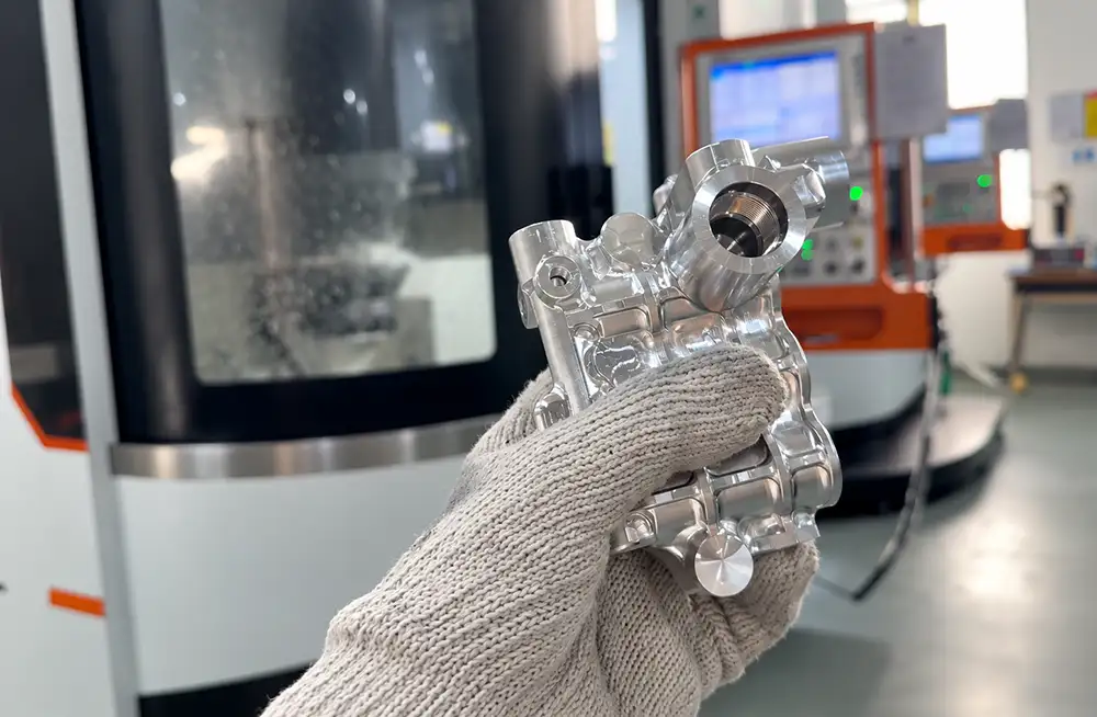
Thin-walled housings, frames, cavity walls, and thin base plates can change shape during machining or after release from a fixture. How can buyers keep wall thickness, form, and mating dimensions within the drawing requirements?
CNC machining thin-walled parts requires more than checking nominal thickness: wall height, unsupported spans, and support conditions also matter. This guide focuses on metal parts made primarily by CNC milling, explaining how design review, workholding, machining sequence, and inspection help control deformation and define a useful quotation request.
IN THIS GUIDE
Understand deformation · Review geometry and material · Plan support and clamping · Sequence material removal · Control the cutting process · Define inspection and your RFQ · Get a Quote · FAQs
Why Do Thin-Walled Parts Deform During CNC Machining?
Cutting and clamping forces. A wall can deflect elastically under cutting force, then recover when the load disappears. Clamping can also alter its shape. Evaluate the tool, workpiece, and fixture together, particularly where the loaded area lacks support. Sandvik Coromant’s thin-wall milling guidance considers wall height relative to thickness when selecting machining strategies.
Residual stress redistribution. A blank may contain residual stress, and machining can introduce additional stress. Removing material changes the balance, potentially causing a shape change that remains after release. This differs from temporary deflection under a cutting load.
Illustrative example: A frame meets its flatness requirement while clamped, but changes shape after unclamping. Compare measurements and support conditions to investigate clamp-induced deformation, residual stress, or both; the observation alone does not identify the cause.
Heat and vibration add further variables. First establish whether the deviation appears during cutting, after unclamping, or after subsequent processing. Each stage suggests different records and controls to examine.
Review Wall Geometry and Material Condition Before Machining
Review the complete structure. Assess wall thickness and height, base-plate spans, openings, unsupported regions, and tool access. Two walls with the same thickness may need different strategies: a short wall supported around its perimeter behaves differently from a tall, isolated wall. Specify the features that matter to assembly rather than asking only for the thinnest achievable wall.
Discuss permitted adjustments. A DFM review can explore local thickening, ribs, cavity depth, or temporary connecting features. A rib retained in the finished product changes the design and needs approval. A temporary support removed during manufacture is a process feature; its removal must still leave the specified final geometry.
Define material and blank condition. When specifying CNC machining materials, state the grade, temper or other supply condition, and any blank requirements. Assess blank selection or approved stabilization treatments against the applicable material specification and final delivery condition. Adding heat treatment is not a universal remedy. Identify which material and dimensions must remain unchanged and which may be discussed.
Use Workholding That Supports the Part Without Distorting It
Support the cutting zone. For a thin housing, identify locating surfaces and regions suitable for carrying clamp loads, then examine sidewalls and the base separately. Support should suit the cutting-force direction. Formed soft jaws, backing, or dedicated supports are candidate approaches to evaluate, rather than interchangeable solutions.
| Workholding item | Question to resolve |
|---|---|
| Location and loading | Are the locating datums clear, and can the clamp locations carry the required loads? |
| Contact and support | Would soft jaws, backing, or dedicated support suit the geometry and cutting direction? |
| Clamped and released states | How will the setup hold securely and reveal any clamp-induced shape change? |
Neither maximum clamping force nor simply loosening the fixture establishes a sound setup. Contact area, force, support, and reliable location need assessment together. Check whether releasing and reclamping changes the relevant geometry before relying on measurements taken in the fixture.
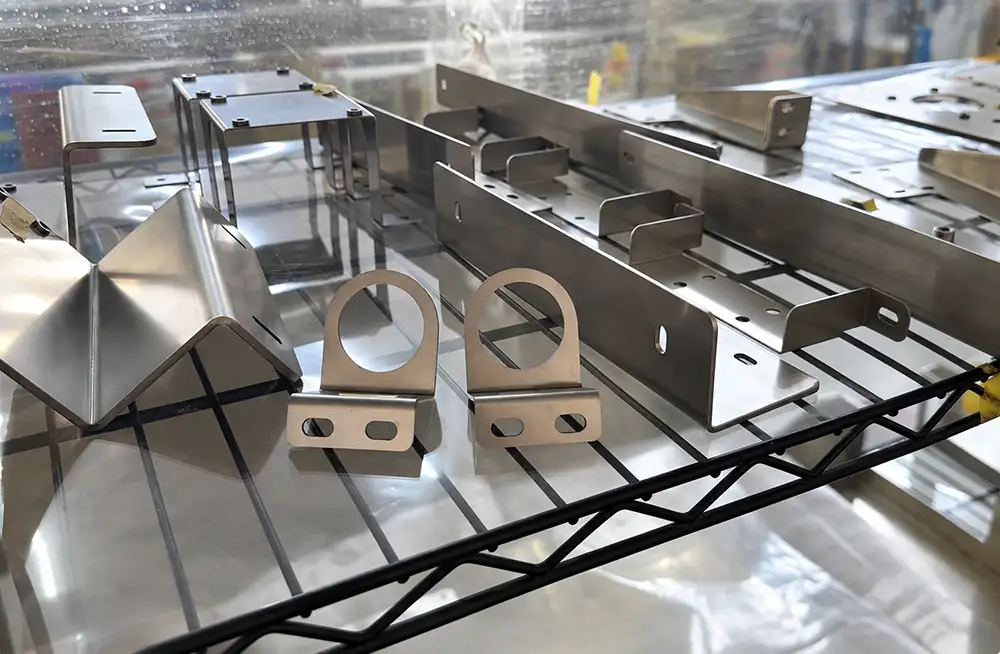
Plan Roughing and Finishing to Preserve Workpiece Stiffness
Remove material in controlled stages. Ask what must be removed now and what should remain temporarily as support. Coordinate roughing and finishing through layered removal, regional machining, or alternating between wall sides. Finishing one side to its final thin section before machining the other may remove useful stiffness too early. Select the sequence for the actual structure.
Plan allowances and support removal. In a thin-base housing, the process review should consider when the base reaches final thickness, which walls still provide support, and when temporary features are removed. Finishing allowances need project-specific evaluation; one allowance cannot suit every material, span, and tolerance.
Check critical transitions. Compare relevant dimensions or form after roughing, after a changed setup, and before final finishing. A study of Al6061-T6 thin-wall frames illustrates why removal sequence and toolpath warrant evaluation, but experimental improvements cannot be promised for every project. Record changes at defined stages so a later deviation can be traced to a meaningful process step.
REVIEW YOUR THIN-WALL DESIGN
Concerned About Deformation in Your Thin-Walled Part?
Share your drawings, material specification, and critical dimensional requirements with Sincere Machining to discuss the manufacturing requirements for your project.
Control Cutting Forces, Heat, and Chatter
Match tooling to material and reach. Review cutting geometry, edge condition, tool overhang, and toolholder rigidity. A short, rigid assembly is desirable where access permits. A long reach may be necessary, but its effect on tool deflection and stability must be considered alongside workpiece support.
Evaluate engagement locally. Entry, exit, corners, radial and axial engagement, and chip thickness interact with the geometry. Reducing feed alone does not necessarily improve the result. The process should address where the part has least support, not just how quickly the program runs. Avoid applying one speed-and-feed recipe to every thin wall.
Manage heat and chips. Match cooling and lubrication to the material, tool, and operation. In cavities, provide for chip removal to limit blockage and recutting. Assess coolant delivery and chip evacuation together; neither high pressure nor a particular toolpath is a universal answer for thin-wall milling.
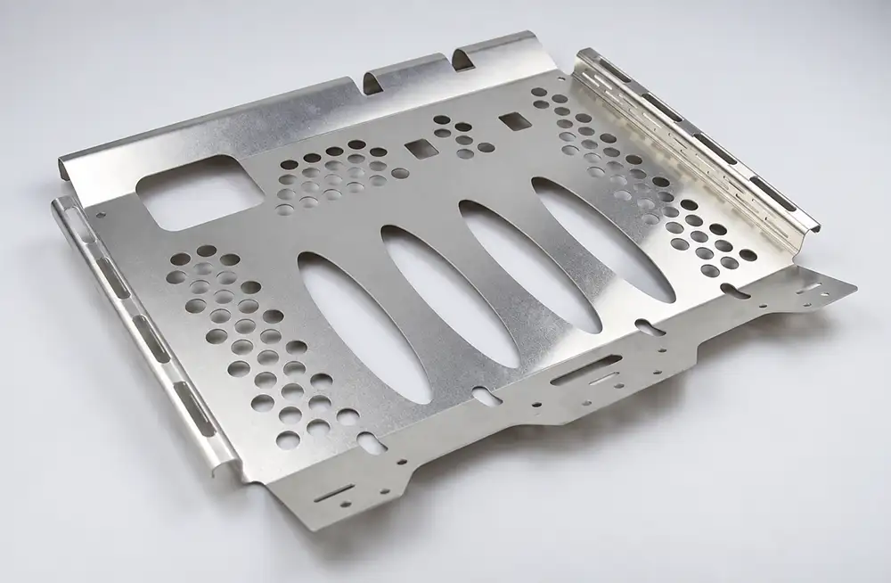
Verify Dimensions After Unclamping and Define Acceptance Conditions
Separate process checks from acceptance. Measurements during machining, checks after release, and final inspection answer different questions. Agree whether acceptance requires a free state, specified support, or defined assembly restraint. For a housing, identify the relevant wall thicknesses, flatness, profiles, and mating features, together with their inspection stages.
Check the inspection fixture. Renishaw’s vision-fixturing guidance highlights secure holding with the minimum necessary force to avoid damage or distortion, alongside repeatable setups. A CMM does not remove fixture effects. Forcing a part flat cannot replace the specified acceptance condition. Sincere Machining’s CNC quality control services describe inspection stages; agree the scope for your project.
| Include in your RFQ | What to identify |
|---|---|
| 3D model and 2D drawings | Current revision, thin-wall locations, critical dimensions, and datums. |
| Material requirements | Grade, condition, and any permitted alternatives for review. |
| Form and fit requirements | Critical wall thickness, flatness, profile, and mating features. |
| Finishing and inspection state | Applicable treatment stage and specified support or restraint. |
| Project arrangements | Prototype and production quantities, target date, and inspection documents. |
Conclusion: Get Your Thin-Walled CNC Parts Reviewed Before Production
Controlling thin-wall deformation starts with understanding when and why shape changes occur. Review geometry and material condition, plan support and material removal, assess the cutting process, and agree the final inspection state. These decisions help turn an outline design into clear manufacturing and acceptance requirements.
SEND YOUR DRAWINGS FOR REVIEW
Planning a Thin-Walled CNC Machining Project?
Send Sincere Machining your 3D CAD files, available 2D drawings, material grade and condition, and prototype or production quantities. Highlight critical wall thicknesses, geometric tolerances, and the required inspection condition so our team can review the manufacturing requirements and prepare a project-specific quotation.
Have you seen deformation in a previous batch? Include the relevant inspection results and explain when the dimensional change was observed.
HAVE THESE READY
01 · Part & material
Current drawings, grade and condition
02 · Critical features
Wall thickness and geometric tolerances
03 · Acceptance state
Finishing stage and support conditions
FAQs About CNC Machining Thin-Walled Parts
What is the minimum wall thickness for CNC machining?
There is no single minimum for every part. Feasibility depends on material, wall height, surrounding geometry, support, and dimensional requirements. Submit the complete design so the supplier can assess a practical wall thickness together with the proposed machining method and agreed inspection condition.
Why does a thin-walled part change shape after unclamping?
The part may recover from clamp-induced elastic deformation, or material removal may have redistributed residual stress. Both effects can be present. Compare records before and after release, machining sequence, and measurement conditions to investigate the change rather than assuming that one cause explains every result.
Does reducing the feed rate always prevent thin-wall deformation?
No. Feed must be considered with tool engagement, chip thickness, cutting geometry, and support. An excessively thin chip can promote rubbing rather than effective cutting and contribute to instability. Evaluate the complete cutting conditions; a lower feed rate alone does not establish a better process.
Do thin-walled parts always require 5-axis CNC machining?
No. Machine selection depends on the surfaces to be cut, tool access, setup requirements, and tolerances. Five-axis machining may suit some geometries, but it does not eliminate the need for support, suitable tooling, and inspection planning. Provide complete drawings before discussing the appropriate machining route.
Can thin-walled parts be machined to tight tolerances?
Assess the specific feature, material, overall dimensions, and acceptance state before confirming capability. A local wall-thickness requirement differs from a flatness or profile requirement across the structure. Where sample validation is agreed, include the critical features and specified support conditions in the inspection plan.

