
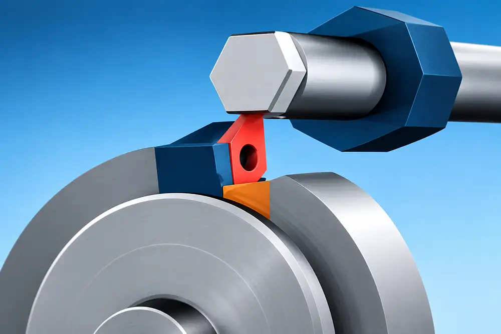
CNC TURNING DESIGN GUIDE
Good CNC turned part design combines rotationally symmetric geometry with adequate rigidity, accessible features, and requirements matched to function. Shoulders, bores, grooves, and threads must accommodate cutting tools, while tolerances, runout, and surface finish must be practical to manufacture and inspect.
Small design decisions can change the process considerably. A slender section may need support; an inaccessible groove may require special tooling; a cross hole may add another setup. These changes affect cycle time, consistency, and cost.
These CNC turning design guidelines explain how to design turned parts with tool access, workholding, and secondary machining in mind, so you can submit clearer drawings and more complete quotation requests.
CNC TURNING DESIGN CHECKLIST
| Design Item | What to Review |
|---|---|
| Main geometry | Is most geometry symmetric around the turning axis? |
| Part rigidity | Can unsupported sections resist cutting forces? |
| Shoulders | Are tool nose radius and relief considered? |
| Internal bores | Can boring tools reach with adequate clearance? |
| Grooves | Can suitable standard grooving inserts be used? |
| Threads | Is there space for runout and tool exit? |
| Tolerances | Are tight limits restricted to critical features? |
| Runout | Are functional surfaces and datum references clear? |
| Workholding | Is there a stable gripping area? |
| Secondary features | Will milling or live tooling be required? |
Review these points together: material, geometry, quantity, equipment, and inspection requirements determine the practical machining route.
IN THIS GUIDE
Main Turning Axis · Rigidity and Support · Shoulders and Relief · Bores and Access · Grooves and Threads · Tolerances and Finish · Workholding and Operations · Key Takeaways · FAQ
Design Around the Main Turning Axis
Turning is well suited to shafts, pins, bushings, sleeves, spacers, and threaded cylindrical components. Outside diameters, inside diameters, steps, shoulders, grooves, and threads can share a common rotational axis, helping organize machining around that axis.
Flats, cross holes, side holes, slots, off-axis threads, and eccentric features change this picture. They may require live tooling, mill-turn equipment, or a separate CNC milling operation. The best route depends on feature access, alignment requirements, quantity, and available equipment.
A mostly cylindrical part can still need a complex process. A few off-axis features may determine how the entire component is held, machined, and transferred.
When reviewing CNC turning services, share every required feature from the start. Removing an unnecessary flat or relocating a side hole can sometimes simplify the route, provided the change preserves function.
Control Length-to-Diameter Ratio and Part Rigidity
Long unsupported sections have less resistance to bending. Cutting forces can push the workpiece away from the tool, causing taper, diameter variation, chatter, and poor surface finish. Thin walls may also deform during gripping or cutting.
Focus on unsupported length, not just overall part length. A tailstock with a live center, steady rest, or follow rest may provide support where the geometry allows. Very slender components may suit Swiss turning. Controlled finishing passes can help, but do not replace adequate support.
There is no universal length-to-diameter limit for every turned part. Material, diameter, tolerance, support method, cutting conditions, and machine configuration all matter. If function permits, shorten slender sections or increase their diameter. Discuss access for supporting equipment before finalizing end features that could prevent its use.
Design Shoulders, Radii, Chamfers, and Tool Relief Correctly
Turning inserts have a tool nose radius. At a shoulder, this radius affects the corner geometry that the tool can produce. An ideally sharp internal 90-degree corner may require a different tool or additional operation, particularly inside a bore.
Allow a practical corner radius where the mating component provides clearance. If a mating face must seat against the shoulder, consider an appropriate relief or undercut. Check the mating part’s chamfer and radius together; otherwise, corner interference can prevent full seating even when both diameters are correct.
Use chamfers to assist assembly, thread starting, deburring, and edge protection. Specify their size when function requires it, but avoid very small or elaborate chamfers without a purpose. Relief grooves also remove material, so check their effect on wall thickness and strength before adding them.
Design Internal Bores and Holes With Tool Access in Mind
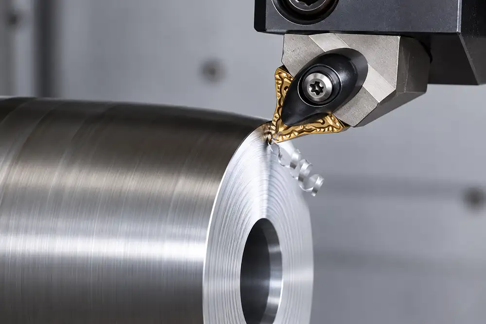
Internal turning is often less rigid than external turning because the boring bar must fit through the opening and extend into the part. Longer tool overhang increases susceptibility to deflection and vibration. A deep bore that looks simple in CAD can therefore create diameter variation or an unacceptable finish.
Small, deep openings are especially restrictive. Blind ends, internal shoulders, grooves, and threads also need room for tool movement, chip evacuation, and inspection. Sandvik Coromant’s internal turning guidance explains why shorter overhang and the largest suitable boring bar improve stability.
- Remove unnecessary bore depth and enlarge openings where function permits.
- Provide clearance for tools to enter, cut, and withdraw.
- Avoid internal features hidden behind a much smaller opening.
- Use suitable standard drill or reamer sizes when the required hole supports those processes.
Need a Design Review Before CNC Turning?
Deep bores, slender sections, internal grooves, or tight tolerances can affect the machining route. Send Sincere Machining your CAD model and drawing, and ask for a manufacturability review before quotation.
Design Grooves and Threads for Standard Turning Tools
Groove width, depth, and location determine tool access and rigidity. Narrow, deep grooves are more demanding, especially inside a small bore. Prefer dimensions compatible with suitable standard inserts when assembly requirements allow, and check clearance behind the cutting edge.
For external and internal threads, specify the thread form, size, pitch, tolerance class, and required engagement length. Provide a starting chamfer and consider thread relief or runout. Requiring a full thread directly against a shoulder without exit space can constrain tool choice.
For blind internal threads, distinguish usable full-thread length from drill depth: the tool and incomplete thread region need additional space. Our guide to designing threaded holes explains related considerations. Prefer standard thread sizes and forms unless a special thread is necessary for the application.
Specify Tolerances, Runout, and Surface Finish Only Where Needed
Turning naturally suits cylindrical dimensions, but achievable CNC machining tolerances depend on material, diameter, unsupported length, setup, and inspection method. Keep tight limits on bearing seats, sealing features, and other function-critical dimensions; use appropriate general tolerances elsewhere.
A diameter tolerance controls size. It does not by itself establish the required relationship to a datum axis. Specify appropriate runout requirements for relevant rotating surfaces, with clear datum references. Circular runout and total runout are different controls; select the one that represents the functional requirement. ASME Y14.5 provides a standardized language for dimensioning and geometric tolerancing.
Define surface finish on mating, bearing, or sealing areas as needed. A surface roughness chart helps interpret parameters, but the application determines acceptance. Excessively demanding finishes can add passes, grinding, honing, polishing, and inspection. State the required parameter and any functional texture requirements rather than asking for every surface to be polished.
Consider Workholding, Part-Off, and Secondary Operations Before Finalizing the Design
Plan where chuck jaws will contact the part during each operation. A component with critical finished surfaces everywhere may be difficult to grip for a second setup. Jaw contact must provide support while limiting deformation and protecting finished areas; thin sleeves deserve particular attention.
Consider the part-off location, stock allowance, burr removal, face finishing, and final length control. The cutoff face may need subsequent machining, so leave a practical way to hold the separated component.
Flats, slots, side holes, cross holes, pockets, and off-axis threads may add milling. Each transfer can introduce setup work and datum alignment challenges. Identify which relationships must be maintained between turned and milled features, and discuss the proposed operation sequence. Before releasing a drawing, review how the part will be held, transferred, finished, and inspected, as well as how each feature will be cut.
Conclusion: Key CNC Turning Design Recommendations
Effective design for CNC turning balances part function with rigidity, tool access, workholding, and inspection. Keep geometry centered on the turning axis where practical, avoid unnecessary slenderness and bore depth, and provide usable shoulders, reliefs, grooves, and threads.
Apply tight requirements where the assembly needs them. Review secondary features and the gripping sequence before release, then submit the same complete requirements with every quote request. This gives suppliers a clearer basis for evaluating the part and explaining its manufacturing cost.
Ready to Review Your CNC Turned Part?
Send your 3D CAD model, engineering drawing, material, quantity, tolerances, and surface finish requirements. Include critical mating features and your delivery target so Sincere Machining can assess your project requirements.
FAQ About CNC Turning Design
What parts are best suited for CNC turning?
Rotationally symmetric shafts, pins, bushings, sleeves, spacers, and threaded cylindrical components are common candidates. Parts with off-axis features may also need live tooling, mill-turn machining, or secondary CNC milling.
How long can a CNC turned part be before deflection becomes a problem?
There is no single limit. Diameter, material, unsupported length, tolerance, support, cutting conditions, and machine configuration matter. A tailstock, steady rest, or Swiss turning may help support slender parts.
Do turned parts need a 2D drawing if a 3D CAD model is available?
Both are usually preferred for precision parts. CAD defines geometry; drawings communicate tolerances, GD&T, runout, finish, threads, and inspection notes. Review files needed for a CNC machining quote before submitting.
When should a turned part use CNC milling as a secondary operation?
Flats, slots, side holes, cross holes, pockets, and off-axis threaded holes may need milling. Whether separate setups or live tooling are appropriate depends on geometry, tolerances, quantity, and available equipment.

