
Engineering drawings for CNC machined parts often include requirements such as Ra 0.8 μm, Ra 1.6 μm, Ra 3.2 μm, Rz values, and surface finish symbols. The numbers may look simple, but specifying them correctly requires more than knowing that a smaller Ra value generally represents a smoother surface.
Designers and buyers also need to understand what the roughness parameter actually measures, which surfaces need the requirement, whether the selected manufacturing process can achieve it economically, how the surface will be inspected, and whether a secondary finish could change the final surface condition. Modern surface-texture standards treat roughness as only one part of a broader surface-texture specification. ASME B46.1, for example, defines surface texture in terms that include roughness, waviness, and lay.
This guide explains how to read a surface roughness chart, understand Ra and Rz values, interpret surface finish symbols, compare CNC machining and finishing processes, and specify practical surface requirements for CNC machined parts.
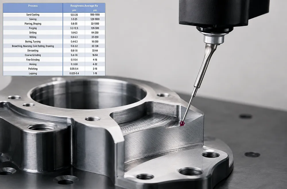
What Is Surface Roughness?
Surface roughness describes the relatively fine-scale irregularities of a manufactured surface. A machined surface that appears smooth to the eye still contains microscopic peaks, valleys, feed marks, and other features created by the manufacturing process. Standards use defined profile parameters to quantify these features rather than relying on visual descriptions such as “smooth” or “fine.” ISO 21920-2:2021 establishes terms, definitions, and parameters for determining surface texture by profile methods.
For CNC machining, the resulting roughness can be influenced by tool geometry, feed, cutting conditions, tool wear, workpiece material, machine rigidity, vibration, built-up edge, and the stability of the overall machining system. Kennametal’s turning guidance, for example, identifies feed and tool nose radius as important theoretical surface-finish variables and notes that actual results can also change with cutting speed, thermal effects, edge condition, chatter, and material properties.
Surface roughness is not exactly the same as surface finish
In everyday manufacturing language, surface finish and surface roughness are sometimes used interchangeably. Technically, however, surface roughness is only one aspect of the broader surface condition.
ASME B46.1 identifies roughness, waviness, and lay as key constituents of surface texture. Roughness deals with relatively fine irregularities, waviness describes larger-spaced variations, and lay describes the predominant direction of the surface pattern.
This distinction matters because two parts can have similar Ra values but different machining marks, lay directions, waviness, scratches, or isolated peaks. Consequently, an Ra value alone does not always describe every surface characteristic relevant to function. Mahr’s explanation of the ISO 21920 framework likewise notes that specifying only Ra and a value will not necessarily correlate with functional behavior in every application.
A surface finish chart is therefore useful as a manufacturing reference, but it should not be interpreted as proof that every surface produced by a given process will have the same roughness.
Surface Roughness Chart: Common Ra Values
The following surface roughness chart provides commonly recognized nominal Ra levels in micrometres and their approximate microinch equivalents. The descriptions and applications are practical engineering guidance rather than guaranteed process capability limits.
| Ra, μm | Approx. Ra, μin | General Surface Description | Typical Planning Application |
|---|---|---|---|
| 12.5 | 500 | Rough machined | Non-critical or clearance surfaces |
| 6.3 | 250 | General machined finish | General-purpose machined parts |
| 3.2 | 125 | Good machined finish | Common CNC-machined surfaces |
| 1.6 | 63 | Fine machined finish | Selected mating and functional surfaces |
| 0.8 | 32 | Very fine machined finish | Precision functional surfaces |
| 0.4 | 16 | Fine finishing territory | Selected bearing, sliding, or sealing applications |
| 0.2 | 8 | Very fine finishing | High-precision or specialized applications |
The microinch values above are rounded nominal equivalents; the exact conversion is approximately 1 μm = 39.37 μin. More importantly, these rows are reference levels, not universal machining-process guarantees. Toolmakers themselves caution that theoretical finish calculations are only planning tools and that actual results vary with the application.
Actual surface roughness can vary significantly with material, tooling, machine condition, cutting parameters, and process strategy, so the values in this chart should be treated as planning references rather than guaranteed process limits.
What does Ra mean?
Ra is an arithmetic-average roughness parameter. At a simplified conceptual level, it represents the arithmetic mean of the absolute profile-height deviations from the mean line over the evaluated profile. KEYENCE similarly describes Ra as the average of the absolute values along the measured length.
Conceptually, Ra can be represented as:
[ Ra=\frac{1}{L}\int_0^L |z(x)|,dx ]
where (z(x)) represents the profile deviation from the mean line and (L) represents the evaluated length. The actual standardized measurement and filtering procedure should follow the governing standard rather than this simplified equation alone; ISO 21920-2 defines the current profile terminology and parameters.
As a practical comparison:
Ra 6.3 μm is relatively coarse compared with the lower values in the chart and may be adequate for many non-critical machined surfaces.
Ra 3.2 μm is a useful reference point for ordinary CNC work, but it should never be assumed to be the automatic result of every CNC milling or turning process.
Ra 1.6 μm represents a finer requirement and may demand more controlled tooling, feed, machining strategy, and inspection than a less restrictive surface.
Ra 0.8 μm and below can sometimes be produced directly by optimized cutting, depending on the material and geometry, while other applications may require grinding, honing, lapping, polishing, burnishing, or another secondary finishing operation. The appropriate process depends on the surface function, geometry, material, and required consistency.
The important rule is that smaller Ra normally means a lower average profile deviation—not automatically a better part. Functional performance may depend on additional texture characteristics, the direction of lay, waviness, individual peaks or valleys, form, dimensional tolerance, or other parameters.
What is Rz, and how is it different from Ra?
Rz is another profile-based surface roughness parameter. Unlike Ra, which averages profile deviations, Rz is based on peak-to-valley/profile-height characteristics and therefore gives greater visibility to pronounced vertical features in the measured profile. The precise mathematical definition and evaluation procedure depend on the standard and edition being used, which is one reason a drawing should identify the applicable specification framework when ambiguity is possible. ISO 21920-2 is the current ISO document defining profile surface-texture parameters.
| Factor | Ra | Rz |
|---|---|---|
| Basic concept | Arithmetic-average roughness | Peak-to-valley/profile-height-based roughness |
| What it emphasizes | Average profile deviation | More pronounced vertical profile features |
| Sensitivity to isolated high/low features | Lower than an extreme-height parameter | Greater |
| Common drawing use | Very common | Also used for functional and manufacturing requirements |
| Direct universal conversion | No | No |
The distinction can matter in practice because an average can hide isolated profile features. KEYENCE gives examples in which Ra is used to evaluate general smoothness while Rz helps reveal surface-height characteristics that may not be obvious from Ra alone.
Most importantly:
Do not use a fixed Ra-to-Rz conversion ratio for precision engineering decisions.
Rules of thumb comparing Rz with Ra do exist, but the relationship changes with the shape of the actual profile. Mahr notes that Rz-to-Ra ratios can vary substantially with surface characteristics, which makes approximate conversions questionable when customer acceptance and manufacturing control depend on the actual parameter.
Therefore, a supplier receiving Ra 1.6 μm should not simply multiply that value by an assumed constant and treat the result as an equivalent contractual Rz requirement. If Rz matters to the function, specify Rz directly.
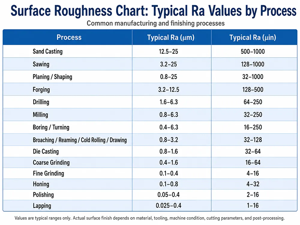
Surface Finish Chart for Common CNC Machining Processes
Different processes create different characteristic surface textures, but no manufacturing process has one fixed Ra value. Feed, cutter geometry, nose radius, abrasive size, tool condition, workholding, material, machine dynamics, stock allowance, and finishing strategy can all change the result. The distinction between roughing and finishing in machining is particularly important because the two stages have very different priorities for material removal, dimensional control, and final surface quality.
The following surface finish chart is intentionally qualitative for that reason:
| Manufacturing Process | Typical Surface-Finish Tendency | Important Considerations |
|---|---|---|
| Rough milling | Relatively higher Ra | Optimized primarily for material removal; step-over, feed, cutter geometry, runout, and vibration matter |
| Finish milling | Lower Ra than roughing in a comparable setup | Finish pass, cutter geometry, feed, step-over, rigidity, and tool condition are important |
| CNC turning | Can range from general to very fine | Feed per revolution and tool nose radius strongly influence theoretical finish |
| Grinding | Fine precision finish | Wheel specification, dressing, feed, machine stability, and material influence results |
| Reaming | Fine internal-hole finish | Tool geometry, stock allowance, alignment, coolant, and chatter control are important |
| Honing | Very fine controlled bore texture | Abrasive selection and process parameters can control bore geometry and texture |
| Lapping | Extremely fine, usually multidirectional finish | Abrasive size, slurry, pressure, plate condition, and material are major variables |
| Polishing | Highly process-dependent cosmetic or functional finish | Appearance and roughness depend strongly on polishing method and starting condition |
These descriptions should be used as manufacturing references rather than guaranteed values.
Actual process examples show why a rigid “process equals Ra value” chart can be misleading. Milling results can vary considerably with material, cutter geometry, feed, step-over, tool condition, machine rigidity, and machining strategy. For parts produced by milling, learn more about Sincere’s CNC milling services and the machining options available for custom precision components.
Grinding is similarly a precision-finishing family rather than a single guaranteed roughness level. UNITED GRINDING describes cylindrical grinding as a precision-finishing process and emphasizes that achievable results depend on the part, application, machine, and setup.
Turning demonstrates the influence of machining parameters particularly well. Kennametal’s theoretical surface-finish calculator uses feed per revolution and corner/nose radius as core variables: generally, reducing feed or using an appropriate larger nose radius can improve the theoretical turned finish, subject to machine stability and the rest of the cutting system. Kennametal also warns that actual results may depart from theory because of cutting speed, heat, wear, built-up edge, chatter, and material characteristics.
This is why a CNC supplier should evaluate the specific component before promising a roughness value. A large accessible milled plane in aluminum, a deep hardened-steel bore, a thin wall that vibrates easily, and a small sealing land can all require different strategies even when the drawing lists the same Ra requirement.
For related manufacturing content, this section can naturally link to Sincere’s CNC Milling, CNC Turning, Honing Process, Types of Reamers, and Surface Finishing resources.
How to Read Surface Finish Symbols on Engineering Drawings
Surface texture is normally specified on a drawing with a standardized graphical symbol plus information describing the required texture and, when necessary, how the surface is to be produced or evaluated.
There is an important standards update that many online surface-finish guides miss:
ISO 1302:2002 is no longer the current ISO standard. ISO officially lists it as withdrawn on December 20, 2021, and identifies ISO 21920-1:2021 as its replacement. ISO 21920-1 specifies the rules for indicating profile surface texture in technical product documentation by graphical symbols.
For U.S.-based practice, ASME currently lists ASME B46.1-2019 (R2026) as the version in effect.
That does not mean every older drawing using ISO 1302 notation suddenly becomes meaningless. Mahr’s guidance on the ISO 21920 transition explains that older dated drawings continue to be interpreted according to the earlier standard applicable to them, while the newer standard applies to new specifications.
The traditional drawing-symbol concepts remain important:
| Symbol Concept | Practical Meaning |
|---|---|
| Basic surface-texture symbol | A surface-texture requirement is specified |
| Symbol indicating material removal required | The required surface is to be produced with material removal |
| Symbol indicating material removal not permitted | The specified surface must not be produced by removing material |
Current ISO 21920 documentation defines the modern rules for these surface-texture indications, and ZEISS’s summary of DIN EN ISO 21920 specifically notes that the symbols communicate, among other things, whether material removal is permissible.
A complete surface-texture callout can communicate much more than a single number. Depending on the applicable standard and functional requirement, the drawing may contain information relating to:
| Drawing Information | What the Manufacturer Needs to Understand |
|---|---|
| Ra, Rz, or another parameter | Which characteristic is controlled |
| Roughness limit | Required numerical acceptance level |
| Manufacturing process | Whether a particular process is specified |
| Lay direction | Direction or pattern of the dominant surface texture |
| Machining allowance | Material reserved for later processing |
| Evaluation/filter information | Conditions under which the texture is evaluated |
| Additional parameters | Further controls where Ra alone is insufficient |
ASME B46.1 specifically treats lay as part of surface texture, while ISO 21920-1 governs graphical indication under the ISO system.
One additional detail is important for engineers working with both old and new ISO drawings. The ISO 21920 series introduced updated terminology and specification rules. Mahr notes, for example, the use of evaluation length and nesting index terminology and explains that section lengths are relevant to parameters such as Rz. Older documentation may instead use terminology associated with withdrawn ISO 4287/4288 conventions.
Therefore:
Surface finish symbols should always be interpreted together with the roughness parameter, numerical limit, and the applicable drawing standard and edition.
A symbol without the rest of the specification can be incomplete. Similarly, reading an old ISO 1302 chart while assuming every detail automatically applies to a new ISO 21920 drawing can introduce unnecessary ambiguity. For a broader explanation of dimensions, tolerances, manufacturing notes, and surface requirements on engineering drawings, see our related guide.
A useful internal link from this section is Sincere’s Engineering Drawing Overview.
What Surface Roughness Should You Specify for CNC Parts?
The most important design principle is straightforward:
Specify the roughness required by function—not the smoothest finish that seems achievable.
A smoother surface is not automatically a better engineering surface. ASME’s treatment of roughness, waviness, and lay as separate surface-texture characteristics demonstrates why one numerical roughness parameter cannot represent every aspect of surface performance.
A practical selection process can start with the function of each surface:
| Surface Function | What to Consider |
|---|---|
| General machined surface | Avoid unusually low roughness unless the function requires it |
| Mating surface | Consider roughness together with fit, dimensional tolerance, form, and assembly requirements |
| Sliding or bearing surface | Consider friction, wear, lubrication, texture direction, and the actual contact condition |
| Sealing surface | Consider leakage risk, contact mechanics, lay, peaks/valleys, and the seal design rather than Ra alone |
| Cosmetic surface | Define visual acceptance separately when appearance matters |
| Precision fit | Evaluate roughness together with size tolerance and geometric requirements |
The fact that Ra alone may not reveal an isolated surface feature is particularly relevant to functional contact surfaces. KEYENCE illustrates cases in which Ra and Rz provide complementary information because an average roughness value can mask localized height features.
How surface roughness affects CNC machining cost
A more demanding roughness requirement can affect much more than the final machining pass.
Suppose a design changes a functional surface from Ra 3.2 μm to Ra 0.4 μm. Depending on the material, geometry, and original process, meeting the lower Ra could require changes in cutting parameters, a dedicated finishing pass, better or different tooling, tighter machine and workholding control, or a secondary operation such as grinding, honing, lapping, or polishing. More restrictive requirements may also justify additional surface-roughness inspection and tighter process control. The exact solution is part-specific rather than automatic.
Even when the required Ra can be achieved directly by CNC machining, achieving it consistently across production can impose more control than merely producing one successful sample. Tool wear and edge condition, for example, can change the actual surface produced during a machining run.
Consequently:
Specifying an unnecessarily low Ra value can increase manufacturing effort and cost without improving the function of the part.
The best drawing is not the drawing with the lowest Ra everywhere. It is the drawing that puts a demanding surface specification only where engineering function requires it.
For difficult surface specifications, Sincere can evaluate the requirement as part of a DFM Review. Our engineering team can assess whether the requested Ra or Rz value is practical with the selected machining process, whether the requirement is unnecessarily restrictive, and whether a secondary finishing operation should be considered before quotation.
Surface roughness vs. surface treatment
Surface roughness and surface treatment should also be kept separate in an RFQ.
A roughness specification such as Ra 1.6 μm defines a surface-texture characteristic. A secondary treatment such as anodizing, plating, passivation, powder coating, or bead blasting describes a subsequent manufacturing or surface-processing operation. Polishing can be both a processing method and a means of changing surface texture, depending on how the requirement is written.
This distinction follows the broader standards concept that surface texture is a geometric property of the surface rather than simply the name of the manufacturing process. ASME B46.1 covers surfaces created by processes including cutting, abrading, coating, etching, plastic deformation, and others while defining how their geometric surface irregularities are characterized.
For that reason, a drawing might legitimately state something such as:
Ra 1.6 μm before anodizing on Surface A.
Or, when final surface condition is important, the specification may need to define inspection after the secondary treatment. The correct stage depends on the engineering intent because the secondary process can alter the resulting surface condition.
An RFQ that merely states “black anodized” does not, by itself, communicate the required machined Ra of a critical bore or sealing face. Conversely, an Ra requirement alone does not communicate coating color, coating specification, masking, or cosmetic expectations. For common anodizing, plating, passivation, powder coating, bead blasting, polishing, and other post-processing methods, see our surface finishing options for CNC machined parts.
This is a natural place to link to Sincere’s Surface Finishing guide.
How to Specify Surface Finish on a CNC Machining RFQ
A good surface-finish specification eliminates guessing before quotation.
For critical parts, provide enough information for the CNC supplier to understand what parameter applies, where it applies, under which standard it is interpreted, and when it must be verified. Current ISO practice separates indication, parameter definition, and specification/verification across the ISO 21920 series, reinforcing the importance of treating a surface requirement as more than an isolated Ra number.
A practical RFQ should address the following:
| RFQ Field | Recommended Information |
|---|---|
| Roughness requirement | For example, Ra 1.6 μm or the required Rz value |
| Parameter | Clearly state Ra, Rz, or another specified parameter |
| Surface location | Identify the exact face, bore, journal, sealing land, etc. |
| Units | μm or μin |
| Drawing standard | Identify ISO/ASME standard and edition where required |
| Processing stage | State whether the requirement applies before or after secondary finishing |
| Surface treatment | Anodizing, plating, passivation, bead blasting, etc. |
| Cosmetic requirement | Define visual criteria separately where necessary |
| Masking requirement | Identify surfaces that must remain untreated |
| Critical final dimensions | Clarify whether dimensions apply before or after finishing |
| Inspection requirement | State any required report, instrument, parameter, or acceptance requirement |
Instead of writing:
Make all surfaces very smooth.
write something measurable, for example:
Ra 1.6 μm on Surface A; other machined surfaces Ra 3.2 μm unless otherwise specified.
Or:
Ra 0.8 μm required only on the sealing surface.
The second approach is particularly useful when only one functional area needs a very fine finish because it allows the manufacturer to avoid applying the same expensive requirement to unrelated faces.
Common surface roughness specification mistakes
Several mistakes repeatedly create unnecessary manufacturing uncertainty:
| Mistake | Why It Creates a Problem |
|---|---|
| Specifying the lowest possible Ra on every surface | Adds manufacturing constraints without proving functional benefit |
| Confusing surface roughness with surface treatment | Anodizing or plating does not replace an Ra/Rz requirement |
| Failing to identify the controlled surface | The supplier cannot determine where the requirement applies |
| Using Ra and Rz interchangeably | They measure different profile characteristics |
| Applying a fixed Ra-to-Rz conversion | Profile shape makes a universal conversion unreliable |
| Ignoring process capability | The specified finish may require a different tool or secondary operation |
| Ignoring the measurement standard | Different parameter definitions or evaluation conditions can cause disputes |
| Specifying roughness without functional justification | Can increase manufacturing effort while providing no useful performance benefit |
The Ra/Rz conversion issue is particularly important. Mahr’s metrology guidance shows that approximate Rz/Ra ratios can vary substantially depending on profile form; therefore, a rough conversion should not be substituted for the parameter that the design actually requires.
Measurement conditions matter too. ZEISS notes that measurement length, measuring direction, filtering, and related evaluation conditions can affect roughness results under the ISO 21920 framework.
How Sincere controls surface finish on CNC machined parts
At Sincere, surface requirements can be reviewed together with the complete manufacturing strategy rather than treated as an isolated number on a drawing.
Depending on the project, the engineering review can consider material, geometry, tool access, toolpath, tool condition, cutting parameters, machining strategy, secondary finishing, and inspection requirements. Projects may involve CNC Milling, CNC Turning, multi-axis machining, or appropriate secondary finishing operations according to the part and specification.
This is especially useful when a drawing contains an unusually low Ra value, an Rz requirement, a critical sealing or mating surface, or a texture requirement that appears difficult to produce with the originally selected machining process.
Send Sincere your drawing and required Ra/Rz values so our engineering team can review whether the specified surface finish is practical for your part before quotation.
How Sincere Controls Surface Finish on CNC Machined Parts
At Sincere, surface requirements are reviewed together with the complete manufacturing strategy rather than treated as an isolated Ra or Rz value on a drawing.
Our engineering review may consider:
Surface Roughness FAQ
What is a surface roughness chart?
A surface roughness chart compares standardized or commonly used roughness levels, usually expressed as Ra or another roughness parameter, so engineers can understand the relative scale of surface requirements. A good chart should be used for reference rather than as proof that a particular machining process automatically produces a specific Ra value. Actual results depend on the machining system, material, tooling, process conditions, and measurement method.
What is the difference between Ra and Rz?
Ra describes arithmetic-average profile deviation, while Rz is based on profile-height/peak-to-valley characteristics and therefore provides different information about pronounced surface features. Two surfaces can have similar Ra values while having meaningfully different profile structures.
What is a good surface finish for CNC machining?
There is no single “best” surface finish for all CNC parts. A general non-critical face, a bearing journal, a sealing face, a precision bore, and a cosmetic panel can require different surface characteristics. The correct requirement is the least restrictive finish that reliably satisfies the part’s functional, assembly, durability, and appearance needs. Standards also recognize that surface texture involves more than roughness alone.
Can Ra be converted directly to Rz?
Not reliably with one universal conversion factor. Approximate ratios are sometimes used for rough comparison, but the relationship changes with the profile geometry. For contractual drawings, process acceptance, and precision engineering decisions, specify and measure the required parameter directly.
What do surface finish symbols mean on engineering drawings?
Surface finish symbols communicate surface-texture requirements and may indicate whether material removal is required or prohibited, which roughness parameter and value apply, the surface lay, machining allowance, process information, and other specification details. For new ISO drawings, ISO 21920-1:2021 is the relevant published standard for indicating profile surface texture; the former ISO 1302:2002 has been withdrawn and replaced. In U.S. practice, ASME lists B46.1-2019 (R2026) as the version currently in effect.
Ultimately, understanding a surface roughness chart is not simply about memorizing that Ra 0.8 μm is smoother in arithmetic-average terms than Ra 3.2 μm. The more useful engineering relationship is:
Part Function → Required Surface Texture → Manufacturing Process → Inspection → Cost
Ra is one of the most widely encountered roughness parameters, while Rz provides complementary information about profile-height characteristics. Neither should be selected merely because a lower numerical value appears “better,” and Ra should not be converted to Rz with an assumed fixed ratio. Surface finish symbols must also be interpreted according to the applicable drawing standard and edition.
For cost-effective CNC production, specify demanding roughness only on the surfaces that need it, identify whether the requirement is Ra or Rz, separate machined surface requirements from secondary treatments, and make the inspection stage clear.
Need CNC Parts With Specific Surface Roughness Requirements?
Send Sincere your 2D drawing, 3D CAD model, material, quantity, required Ra/Rz values, surface treatment, and inspection requirements. Our engineering team can review your surface specifications before quotation and evaluate an appropriate machining and finishing strategy for the part.

