
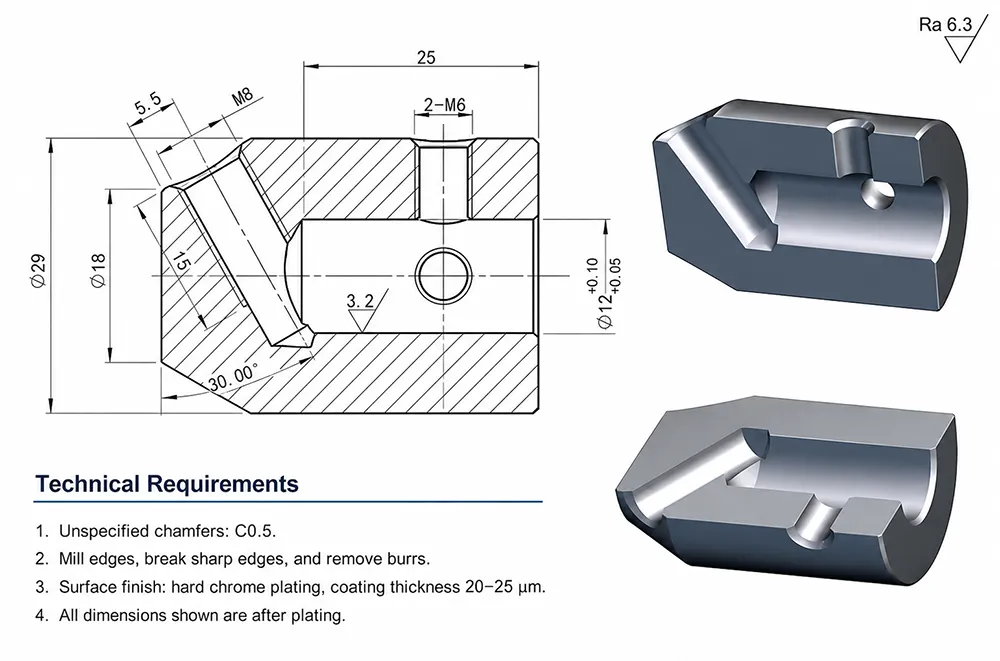
Good CNC part design considers tool access, wall thickness, internal corner radii, hole depth, thread geometry, tolerances, and feature size. Designs that ignore these limitations may require smaller or longer cutting tools, additional setups, special tooling, slower machining parameters, or secondary processes, increasing manufacturing complexity, cost, and lead time. Autodesk notes that forcing a milling cutter into tight internal corners can increase tool engagement, chatter, and surface-finish problems, while Sandvik identifies tool overhang and vibration as important constraints in deep-feature machining.
This CNC machining design guide explains the key rules engineers and product designers should consider when designing milled and turned parts, including internal corners, cavities, thin walls, holes, threads, undercuts, tolerances, chamfers, and engraving.
Key CNC Design Rules
| Design feature | General recommendation |
|---|---|
| Internal corners | Add radii compatible with practical end-mill sizes |
| Deep cavities | Avoid unnecessarily deep and narrow geometry |
| Thin walls | Keep walls sufficiently rigid for cutting and clamping |
| Holes | Prefer common drill diameters where function allows |
| Threads | Avoid unnecessary thread depth, especially in blind holes |
| Tolerances | Tighten only dimensions that affect function |
| Undercuts | Simplify them or confirm tool access before release |
| Text | Use simple, adequately sized recessed lettering |
A part can be technically machinable without being economical to manufacture. Geometry influences tool access, cutter rigidity, machining strategy, workholding, tool changes, inspection requirements, and the number of setups required to complete the part. Deep pockets, small internal radii, thin walls, and unnecessarily tight tolerances can all increase machining time or require additional operations. These design decisions therefore have a direct effect on CNC machining cost.
Design Internal Corners, Cavities and Pockets for Tool Access
One of the most important principles in design for CNC machining is simple: the cutting tool must physically reach the material you want removed, while remaining rigid enough to cut it accurately.
Internal corner radii. Standard end mills are rotating tools, so a milled internal corner naturally inherits a radius related to the cutter geometry. A conventional end mill therefore cannot produce a perfectly sharp, zero-radius 90-degree internal corner simply by following the walls of a pocket.
The design should not merely make the corner radius equal to the cutter radius. Autodesk warns that forcing a cutter into an internal corner where the machining radius is extremely tight can sharply increase engagement, creating chatter and potentially degrading the surface finish. Its CAM guidance uses blended cutting paths specifically to reduce these problems.
Where the functional design permits it, use a larger internal radius. This generally gives the machinist more freedom to select a larger, stiffer cutter and can reduce the amount of rest machining with smaller tools. Autodesk likewise advises designers to consider larger fillet radii when tool availability is uncertain because larger radii permit larger-diameter tooling.
Deep cavities and pockets. Depth is another major constraint. Deep pockets require longer tool reach, and increasing the ratio between tool overhang and tool diameter reduces rigidity. Sandvik reports that milling vibration becomes more pronounced when overhang exceeds roughly four tool diameters, while Autodesk similarly identifies deep pockets as a common source of tool deflection.
For designers, the practical lesson is not that every cavity needs one universal maximum depth. It is to avoid making a pocket both deep and narrow unless that geometry is functionally necessary.
| Pocket geometry | Design assessment |
|---|---|
| Shallow and relatively open | Preferred |
| Deeper with good lateral access | Usually practical |
| Deep and narrow | More difficult; tool reach and rigidity become important |
| Very deep with restricted access | Engineering review recommended |
Deep-feature machining can require altered cutting strategies because vibration and long tool overhang become limiting factors. Sandvik, for example, describes plunge milling as one alternative for deep cavities and long-overhang situations.
Choose Appropriate Wall Thickness for CNC Machined Parts
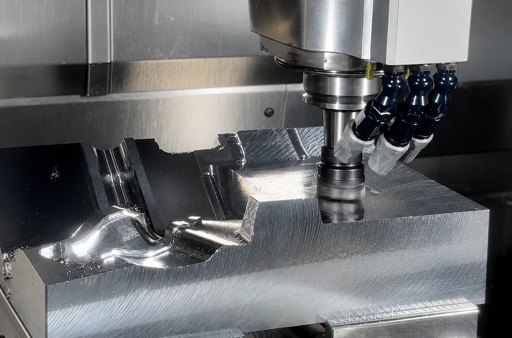
Thin walls are possible with CNC machining, but they are less rigid than surrounding bulk material. As material is removed, cutting forces can deflect the wall away from the tool. Research on thin-walled milling repeatedly identifies low structural rigidity and cutting-force-induced deformation as major causes of dimensional and surface errors.
Clamping introduces another concern. A thin or flexible section may deform while the component is held in a fixture and then move after the clamping force is released. Heat generated during machining can further affect sensitive geometries, particularly when the workpiece has limited stiffness.
This is why there is no single minimum CNC wall thickness that is correct for every component. A practical limit depends on material, wall height and length, surrounding support, cutter engagement, workholding, required tolerance, and surface-finish requirements. Studies of thin-wall machining likewise treat deformation as a combined problem involving geometry, cutting force, machining strategy, and support conditions rather than a single thickness value.
Different materials also behave differently:
| Material type | CNC wall design consideration |
|---|---|
| Aluminum | Generally machinable, but tall or unsupported thin walls can still flex |
| Stainless steel | Cutting conditions and forces can make low-rigidity geometry more demanding |
| Engineering plastics | Heat, flexibility, and clamping deformation may become significant |
Where a thin wall is functionally necessary, increasing local support, reducing its unsupported height, or discussing the machining sequence with the supplier is often more useful than applying a generic thickness rule.
Design Holes and Threads for Standard CNC Tooling
Holes are simple features geometrically, but their diameter, depth, tolerance, entry conditions, and whether they are blind or through all affect how they are machined. Sandvik identifies hole diameter, hole depth, and required hole quality as fundamental variables in drilling-tool selection.
Use standard hole sizes where possible. When the function does not demand a special diameter, selecting a size compatible with readily available drilling, reaming, or boring tools can simplify process planning. In practical production, avoiding unusual diameters can reduce the need for additional interpolation, custom tooling, or secondary sizing operations.
Avoid excessively deep holes. As the depth-to-diameter ratio increases, chip evacuation, coolant delivery, tool stability, and drill selection become more important. Sandvik’s drilling documentation explicitly states that maximum hole depth is related to both drill diameter and tool design, and its commercial drill families use different depth ranges depending on application and material.
This is why “How deep can CNC drill?” has no universal numerical answer.
Through holes are usually simpler than blind holes. A through hole gives the tool an exit and generally makes chip evacuation less restrictive. A blind hole ends inside the component, so the designer must consider the drill-point geometry, required usable cylindrical depth, chips, and clearance below any thread.
Do not assume that the nominal CAD hole depth equals the full usable straight-wall depth. A conventional drill produces geometry at the bottom corresponding to its point shape.
Threaded holes require additional planning. Use standard thread forms and pitches unless the assembly genuinely requires something unusual. Avoid specifying substantially more full thread depth than the joint requires, especially in blind holes. Blind threaded holes also need sufficient clearance below the required thread depth for the tool and chip evacuation. For more detailed recommendations on tap-drill sizes, blind holes, and thread production methods, see our guide to threaded hole machining.
Avoid Difficult Slots, Undercuts and Very Small Features
Feature size determines tooling.
A narrow slot generally requires a smaller cutter or a specialized slotting tool. Smaller and longer-reaching cutters have less rigidity than larger tools, while deep slotting can involve higher forces and greater sensitivity to vibration. Sandvik distinguishes shallow closed slots from long or deep slots partly for these reasons and recommends different cutter strategies depending on the geometry.
For this reason, avoid making a slot narrower than necessary for its function.
Undercuts deserve particular attention because the cutting surface may not be accessible to a conventional straight end mill. Depending on the geometry, undercut machining may require lollipop, disc, dovetail, T-slot, or other specialty tooling. Autodesk specifically lists lollipop, disc, barrel, and dovetail cutters as tools suitable for three-axis undercut machining.
An undercut may also force a different part orientation or an additional setup. Therefore, before adding one, ask whether the same function could be achieved using an open slot, removable component, through feature, or more accessible geometry.
Very small features create similar tradeoffs. Tiny holes, delicate pins, miniature pockets, and narrow grooves are not automatically impossible to machine—micro-cutting tools exist—but reducing feature size increases the importance of tooling, spindle runout, reach, chip control, and process stability. Sandvik, for example, offers specialized microdrills down to extremely small diameters, illustrating that such features require purpose-specific tooling rather than ordinary drilling practice.
Unsure Whether Your Part Is CNC-Machinable?
Send us your CAD model and engineering drawing. Our engineering team can review thin walls, deep cavities, small holes, undercuts, difficult tool access, and critical tolerances before quotation.
Upload CAD Files for Review →Review wall thickness and possible deformation risks.
Check tool reach, rigidity and machining accessibility.
Evaluate drill diameter, depth and tool availability.
Identify features requiring special tooling or setups.
Review whether cutting tools can reach critical features.
Check tolerance feasibility and inspection requirements.
Apply CNC Machining Tolerances Only Where Needed
One of the most expensive habits in CNC part design is applying tight tolerances to dimensions that do not need them.
A dimension should be controlled according to function: fit with a mating component, bearing or seal performance, alignment, location, interchangeability, or another genuine engineering requirement. Tightening every dimension does not automatically create a “better” part.
Tighter tolerances can require additional finishing passes, different tooling, more careful process control, and more inspection. Depending on the requirement, secondary operations may also become necessary. CNC machining guidance from industry sources specifically warns that overly restrictive tolerances may require modified programs, special cutters, grinding, or EDM, increasing both cost and lead time.
For that reason, use the supplier’s normal machining capability for non-critical dimensions and reserve tighter limits for features whose function actually depends on them.
The same principle applies to geometric requirements. When the real requirement is that a surface remain flat, two faces stay perpendicular, a hole pattern maintain its true position, or a rotating feature meet a runout requirement, simply tightening every ± dimension may not communicate the design intent effectively.
This is where geometric dimensioning and tolerancing (GD&T) becomes useful. The ASME Y14.5 Dimensioning and Tolerancing standard establishes standardized symbols, rules, definitions, and practices for communicating dimensional and geometric requirements on engineering drawings and digital product definitions.
For practical machining considerations, see our CNC machining tolerances guide. If you need help interpreting individual controls such as flatness, perpendicularity, position, or runout, our GD&T symbols guide explains the commonly used symbols and their meanings.
Design Chamfers, Fillets, Text and Engraving Carefully
Small details are easy to overlook during CAD design, but they can add meaningful machining time when multiplied across many edges or surfaces.
Chamfers and edge breaks are useful for deburring, assembly, handling, and protecting sharp edges. However, there is rarely a manufacturing advantage in specifying many different chamfer sizes unless each serves a functional purpose. Standardizing edge treatments can simplify both machining and inspection.
External fillets are different from internal corner radii. Internal radii directly constrain the cutter that can enter a pocket. External corner fillets do not create the same tool-access problem because the tool approaches the outside of the geometry. Autodesk notes this distinction when discussing design for manufacture and explains that cutter engagement differs substantially between internal and external corners.
Text and logos should also be designed as machining features. Extremely small characters, thin strokes, intricate fonts, and unnecessary engraving depth can require small tools and long toolpaths. For conventional mechanical engraving, simple recessed text is generally preferable to complex raised lettering because raised text requires removing the surrounding material rather than simply tracing the characters.
Industry machining guidance recommends simple fonts and sufficiently robust character geometry for milled text, and also notes that engraving adds machining time.
CNC Machining Design Checklist Before Sending an RFQ
Before requesting a quote, review the model from the machinist’s point of view. Ask not only, “Does this geometry satisfy the product function?” but also, “Can a rigid cutting tool reach every feature without unnecessary setups or special processes?”
| Check | Question |
|---|---|
| Internal corners | Are the radii compatible with practical cutter sizes? |
| Cavities | Are any pockets deeper or narrower than necessary? |
| Tool access | Can the cutting tool reach all machined surfaces? |
| Walls | Are tall or thin walls sufficiently supported? |
| Holes | Are unusual diameters actually required? |
| Deep holes | Is the depth necessary for function? |
| Blind holes | Is allowance provided for drill-point and chip clearance? |
| Threads | Is the specified full thread depth necessary? |
| Slots | Could narrow slots be widened without affecting function? |
| Undercuts | Can inaccessible geometry be simplified? |
| Tolerances | Are tight tolerances restricted to critical dimensions? |
| GD&T | Are geometric requirements stated clearly where needed? |
| Text | Are characters large and simple enough to machine reliably? |
| Drawing | Are critical dimensions, threads, finishes, and inspection requirements defined? |
A manufacturable CAD model should also be supported by a clear engineering drawing whenever tolerances, thread specifications, surface finishes, datums, inspection requirements, or other information cannot be communicated adequately through nominal 3D geometry alone. ASME’s dimensioning and tolerancing framework exists specifically to provide a standardized language for communicating such design requirements.
For components with deep cavities, thin walls, difficult tool access, undercuts, tight tolerances, or other manufacturing risks, a pre-production DFM review can identify potential machining, workholding, tolerance, and process issues before the design is released for production. Resolving these problems before machining begins is usually more efficient than modifying the part after tooling, programming, or inspection requirements have already been established.
Need a Design Review Before CNC Machining?
Send us your CAD files, engineering drawings, material, quantity, surface-finish requirements, and critical tolerances. Our engineering team can review the design before quotation and identify potential machining issues.
Upload your drawings and project requirements. Our team will review them and prepare a machining quotation.
Request a CNC Machining Quote →Frequently Asked Questions About CNC Machining Design
What is the minimum wall thickness for CNC machining?
There is no universal minimum wall thickness that applies to every CNC-machined part. The practical limit depends on material stiffness, wall height and length, surrounding support, workholding, cutter geometry, machining parameters, and required tolerances. Thin-walled machining research shows that low rigidity makes components more susceptible to cutting-force-induced deformation, so a wall that works in one geometry or material may be unsuitable in another.
Why do CNC machined parts need internal corner radii?
Milling cutters rotate around an axis, so a conventional cylindrical end mill naturally leaves a radius in an internal corner. Extremely tight radii also increase tool engagement and can contribute to chatter or poor surface finish. Where function permits, larger radii provide more freedom to use larger, more rigid cutters and reduce the need for additional rest machining.
How deep can a CNC machine make a hole?
Maximum practical hole depth depends on the hole diameter, workpiece material, drill design, machine capability, coolant delivery, required tolerance, and whether the hole is blind or through. Sandvik explicitly treats drill depth as a function of tool and hole diameter, with different drill families designed for different depth ranges. Deep holes therefore should be reviewed as a tooling problem rather than designed around one universal depth-to-diameter limit.
Do tighter tolerances make CNC machining more expensive?
Yes, in most cases. Tight tolerances can require additional machining passes, slower or more controlled finishing operations, specialized tooling, additional measurement, and potentially secondary processes. They may also reduce the acceptable process window. Apply tight tolerances only to dimensions or geometric characteristics that are important to function, fit, assembly, or interchangeability.
What files should I send for a CNC machining quote?
Send a high-quality 3D solid model, commonly in a neutral format such as STEP/STP or, where supported by your supplier’s workflow, IGES or Parasolid. Autodesk’s current CAD documentation confirms support for STEP, IGES, and Parasolid formats in modern engineering workflows. Also include a 2D engineering drawing when critical tolerances, GD&T, threads, surface finishes, or inspection requirements must be specified, together with the required material, quantity, and finishing requirements.

