
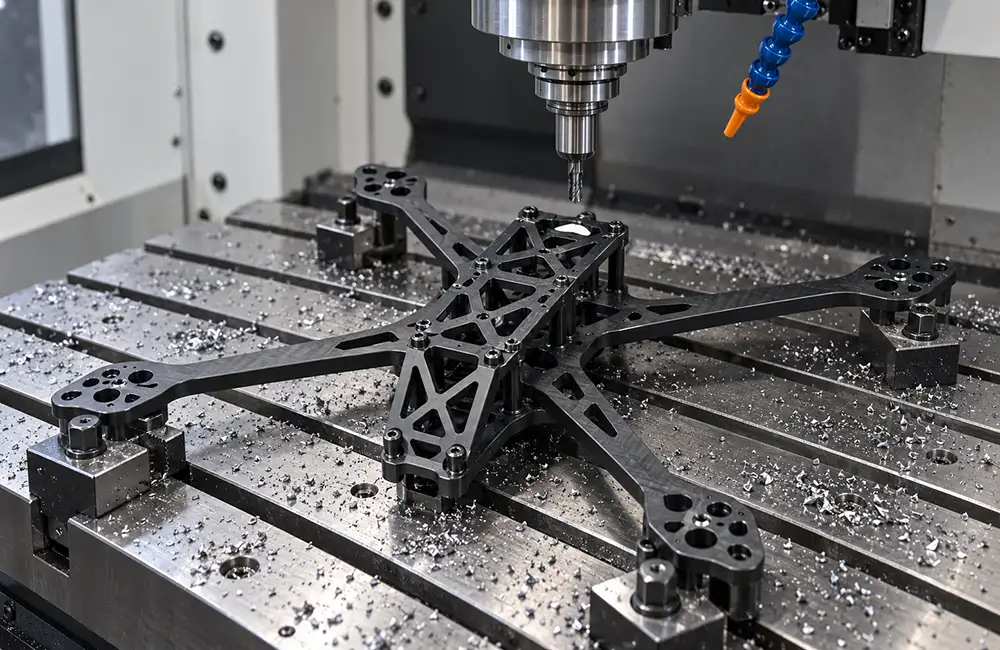
Motor mounts, gimbal brackets, arm connectors, and electronics housings offer opportunities to reduce mass. The challenge is removing material while preserving mounting interfaces, structural requirements, and a design that can be manufactured and inspected.
This guide explains how to design lightweight CNC machined drone parts, focusing on custom metal components rather than complete aircraft or consumer accessories. It covers material selection, weight-reduction pockets, ribs, machining limits, and prototype validation. A lighter component must still meet its requirements; its weight reduction alone does not establish an improvement in flight endurance.
IN THIS GUIDE
Set weight and function targets · Compare material requirements · Plan pockets and ribs · Check machining feasibility · Protect critical interfaces · Validate and prepare your RFQ · Get a Quote · FAQs
Define Weight Targets and Functional Requirements First
Establish a comparable baseline. Record current weight, target weight, and the configuration being weighed: the bare machined part, finished part, or assembly including screws and inserts. Compare candidate designs on the same basis. Adding hardware to a lighter metal body can change the total result.
Define loads and stiffness. Specify applicable loads, mounting constraints, allowable displacement, and required vibration or fatigue validation. Design optimization distinguishes minimizing mass from maximizing stiffness; include displacement, modal-frequency, or buckling constraints where relevant. A weight target alone is therefore insufficient.
Illustrative design example: For a gimbal bracket, first mark the camera mounting face, locating holes, and aircraft attachment interfaces. Identify regions that may change around them. The resulting design input should state the weight baseline, target, fixed interfaces, and performance conditions before anyone removes material.
Choose Materials for Strength, Stiffness, and Weight
Compare specific aluminum grades and tempers. Evaluate 6061-T6/T651 and 7075-T6/T651 against strength, density, elastic modulus, corrosion requirements, and finishing needs. Kaiser Aluminum’s 6061 alloy data and 7075 alloy data show that 7075 has slightly higher density and a similar elastic modulus, while the relevant strength values differ substantially.
Higher strength does not make an unchanged shape lighter or increase stiffness in the same proportion. A stronger alloy may enable an approved geometry change, but that complete design still needs assessment. Replacing 6061 with 7075 is not an automatic weight-saving upgrade.
State the supply condition. When selecting CNC machining materials, specify grade and temper rather than simply “aluminum.” Confirm environmental, joining, and surface-treatment requirements. If material is fixed, identify what cannot change; if selection remains open, submit candidate grades. Compare complete parts meeting the same requirements, with availability and machining cost confirmed through a quotation.
Reduce Weight with Pockets, Ribs, and Local Reinforcement
Remove material from suitable regions. Identify protected connections and primary load paths before introducing pockets, openings, or a revised outer profile. On the example gimbal bracket, preserve the camera interface and attachment areas while exploring material removal between them. Do not treat every apparently unused surface as structurally unnecessary.
| Illustrative candidate design | What to compare |
|---|---|
| Uniformly thinner bracket | Check attachment regions and displacement against the same requirements. |
| Weight-reduction pockets | Review pocket positions, retained perimeter, and mounting areas. |
| Pockets with connecting ribs | Evaluate rib position, cross-section, tool access, and structural response. |
These are comparison options, not a ranking. The ribbed design is not automatically best. Evaluate them using the same loads, constraints, material data, and acceptance criteria. For example, one candidate could leave a bridge between two pockets, while another retains a perimeter frame. The design team should compare their responses rather than choosing by appearance or pocket count.
Review transitions as part of the structure. Discuss pocket corners, rib connections, and changes in local thickness together. Radii, rib width, and cavity depth affect both the structure and cutter access. Keep material around interfaces where analysis requires it, and avoid making the whole bracket thinner simply to meet a mass target.
Keep Lightweight Features Practical for CNC Machining
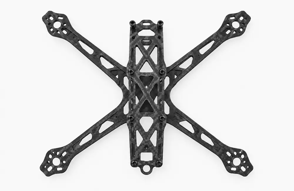
Provide tool access. Use internal pocket radii that suit the proposed cutter, avoid unnecessary deep narrow cavities, and allow room for cutter entry, holder clearance, and chip removal. Protolabs Network’s CNC design guidance explains how tool shape, reach, and access constrain milled features. Five-axis equipment does not make every inaccessible cavity practical.
Assess walls as complete features. Review thickness together with wall height, unsupported span, and clamping locations. Discuss locating surfaces, holding areas, or temporary process supports during a DFM review. Changes retained in the finished component require design approval; temporary supports must be removed without compromising final requirements.
Compare weight savings with manufacturing effort. More pockets may leave the original blank size unchanged while adding cutting time. Thin walls, complex cavities, extra setups, and inspection can also increase effort. A lighter finished part is not necessarily cheaper to machine. Compare CNC machining cost through quotations for complete, acceptable candidate designs rather than their CAD masses alone.
TURN YOUR DESIGN INTO A QUOTATION
Have a Lightweight Drone Part Design Ready?
Share your drawings, material requirements, target part weight, and order quantity with Sincere Machining to discuss manufacturability and request a project-specific quote.
Preserve Mounting, Threaded, and Functional Interfaces
Mark protected features. For common CNC-machined drone parts, identify mounting faces, locating and mating holes, threaded regions, and required contact surfaces. Make their position and acceptance requirements clear before modifying nearby geometry.
| Part example | Interfaces to protect during review |
|---|---|
| Motor mount | Motor mounting face, hole relationships, and arm connection regions. |
| Gimbal bracket | Camera locating features, assembly clearance, and fastener access. |
| Electronics housing | Internal mounting points, cover fit, and specified sealing or thermal-contact regions. |
Define final dimensions. Separate critical fits from noncritical pocket contours and state whether acceptance applies before or after finishing. If inserts or additional fasteners are introduced, include their weight, installation space, and cost. For the bracket example, the protected camera interface remains a design requirement throughout the comparison. Check that a new rib also leaves room to insert and tighten the camera fasteners; fitting the camera is only one part of assembly access.
Validate the Design and Prepare It for Production
Compare designs consistently. Assess mass, displacement, stress, and other required indicators using consistent loads, constraints, and material parameters. Topology optimization or generative design must include milling directions, tool access, and manufacturing restrictions. Geometry suited to additive manufacturing is not automatically machinable.
Structural analysis and applicable performance validation belong to the design team or its appointed engineers. A machining DFM review addresses manufacturing considerations; it is not aircraft performance certification.
Validate prototypes before batch release. Check actual weight, critical dimensions, assembly interfaces, and agreed functional requirements. Record the finishing stage and support or assembly condition used. A simulation image alone does not demonstrate acceptance. For deformation-control considerations, review thin-wall machining and deformation control, including staged removal and checks after unclamping.
Prepare an RFQ package for a DFM review that describes the current design and permitted changes. Keep candidate versions clearly named, and identify the version authorized for manufacture once the design and purchasing requirements are confirmed:
| Submit with your RFQ | Information to include |
|---|---|
| Current model and drawings | Revision, critical interfaces, and regions permitted to change. |
| Weight target | Current and target weight, with a consistent comparison basis. |
| Material and finishing | Grade, condition, surface treatment, and options for discussion. |
| Acceptance requirements | Critical dimensions, inspection state, and required reports. |
| Purchasing plan | Prototype quantity, expected production volume, and target delivery date. |
Conclusion: Get Your Lightweight Drone Parts Reviewed for CNC Machining
Effective lightweight design combines a clear weight target with suitable materials, carefully placed pockets and ribs, and protected functional interfaces. Confirm machining feasibility and validate the candidate against its requirements before production. Those decisions provide a stronger basis for a quotation than asking for the lightest possible part.
SHARE YOUR DRAWINGS AND WEIGHT TARGET
Planning a Lightweight CNC Drone Parts Project?
Send Sincere Machining your 3D CAD files, available 2D drawings, material requirements, and prototype or production quantities. Include your target part weight, critical interfaces, and inspection requirements so our team can review manufacturability and prepare a project-specific quotation.
Still comparing designs? Share the candidate versions and identify which requirements must remain unchanged.
HAVE THESE READY
01 · Drawings & quantities
Current revision and candidate designs
02 · Weight & interfaces
Target weight and areas to preserve
03 · Material & acceptance
Grade, condition, finish and inspection
FAQs About Lightweight CNC Machined Drone Parts
How much weight can CNC machining remove from a drone part?
There is no universal reduction percentage. Compare candidate geometry against the original design while retaining required interfaces and performance constraints. CAD mass calculations can help screen options, but final prototype weight should be measured in the same finishing and assembly configuration used for the baseline.
Is 7075 aluminum always better than 6061 for lightweight drone parts?
No. Compare the specified temper, strength, stiffness, density, environment, and finishing requirements. A stronger alloy does not automatically reduce the weight of an unchanged shape. Any weight-saving opportunity must be assessed through acceptable geometry changes and validation of the complete candidate design against its requirements.
What is the minimum wall thickness for CNC-machined drone parts?
A practical minimum depends on material, wall height, unsupported span, surrounding structure, support, and tolerances. Submit the complete model and drawings for assessment. A wall thickness achieved on one example is not a general capability promise for other geometries, inspection states, or production requirements.
Do lightweight drone parts require 5-axis CNC machining?
Not necessarily. Select the machining route according to surfaces, tool approach, holding arrangements, and dimensional requirements. Lightweight design does not inherently require five-axis equipment. Closed lattices intended for additive manufacturing may remain unsuitable for milling, so assess manufacturing access before finalizing an optimized shape.
Does reducing part weight also reduce CNC machining cost?
Not always. Finished weight, blank consumption, and manufacturing effort are different measures. Extra pockets or thin sections may add cutting time, setups, tooling, and inspection without reducing blank size. Compare complete quotations for designs meeting the same functional and acceptance requirements before drawing a cost conclusion.

