
Engineering drawings specify tolerance to define how much a manufactured dimension can vary from its nominal size. Tolerance ensures parts still fit and function despite inevitable machining variations. For example, a callout “Ø25.00 ±0.05 mm” means the actual diameter may range from 24.95 to 25.05 mm. Tolerance is essential: if it is too tight most parts fail inspection and costs soar, whereas if it is too loose parts may not assemble or function properly. Two common ways to express dimensional tolerance are unilateral tolerance (one-sided) and bilateral tolerance (two-sided). Unilateral tolerance permits size variation only in one direction from the nominal, while bilateral tolerance allows variation on both sides. This article defines each, compares them, gives examples, and discusses their impact on CNC machining, inspection, and cost.
What Is Tolerance in Engineering Drawings?
For a broader engineering drawing reference, ASME Y14.5 Dimensioning and Tolerancing establishes widely used rules and practices for interpreting dimensioning and tolerancing requirements. No machining or fabrication process can achieve a perfect size every time, so designers include tolerances on drawings to ensure parts still fit and function even with small deviations. For instance, a dimension specified as 25.00 ±0.05 mm communicates a nominal target of 25.00 mm, an upper limit of 25.05 mm, and a lower limit of 24.95 mm. Any part whose actual size falls within that range is considered in tolerance; parts outside that band must be reworked or scrapped. Tolerances influence cost and quality: very tight tolerances require slow machining, precise tooling and frequent inspection, driving up cost, while overly loose tolerances can lead to assemblies that bind or fail. Properly chosen tolerances balance functional requirements (fit, clearance, strength) with manufacturing capability and cost.
What Is Unilateral Tolerance?
Unilateral tolerance is a dimensioning scheme where the allowable variation is entirely on one side of the nominal size. In a drawing, one limit is zero and the other is nonzero. For example, “Ø25.00 +0.10/–0.00 mm” means the feature can only grow to 25.10 mm or stay at 25.00 mm – it cannot undersize below the nominal. Conversely, “Ø25.00 +0.00/–0.10 mm” means it can only shrink (down to 24.90 mm) and never exceed 25.00 mm. By fixing one side at zero, unilateral tolerance ensures the part does not deviate in the forbidden direction. Engineers use unilateral tolerances when a feature has a critical one-sided limit. For example, in an interference fit one might say “Shaft Ø10.00 +0.00/−0.02 mm”, ensuring the shaft is never larger than 10.00 mm. As one source explains, designers choose unilateral tolerance when functionality depends on preventing change in one direction. Typical cases include interference fits (preventing a shaft from growing too large) and strength-critical dimensions (preventing a wall from becoming too thin).
Unilateral Example: Hole diameter specified as Ø10.00 +0.02/–0.00 mm. This means the hole can be 10.00–10.02 mm (never smaller than 10.00), guaranteeing sufficient clearance.
What Is Bilateral Tolerance?
Bilateral tolerance permits variation on both sides of the nominal dimension. In notation, it is often written with a “±” sign (for symmetric variation) or as two unequal offsets. For example, “Ø25.00 ±0.05 mm” means the part may be as small as 24.95 mm or as large as 25.05 mm. In drawings, the entry “20.00 ±0.05 mm” indicates ±0.05 mm tolerance around 20.00. Bilateral tolerances allow the feature to deviate either way and are common for routine external dimensions. Symmetric bilateral tolerances (± value) are the simplest and most used for non-critical sizes. As an example, a length callout of 50.00 ±0.10 mm means the actual length can be 49.90–50.10 mm. In summary, bilateral (±) tolerances “surround” the nominal on both sides and are appropriate when a dimension has no strict one-sided constraint.
Unilateral vs Bilateral Tolerance: Main Differences
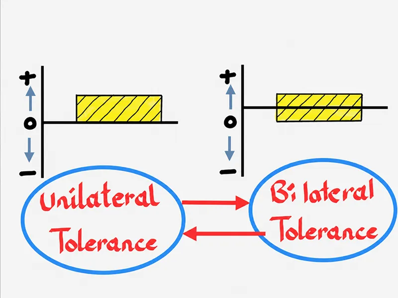
A bilateral tolerance (left) provides equal variation above and below the nominal size, whereas a unilateral tolerance (right) shifts the tolerance zone entirely above or below the nominal.
| Factor | Unilateral Tolerance | Bilateral Tolerance |
|---|---|---|
| Direction | Variation allowed in one direction only | Variation allowed in both directions |
| Example | 25.00 +0.05 / -0.00 mm | 25.00 ±0.05 mm |
| Size range | 25.00–25.05 mm | 24.95–25.05 mm |
| Best for | Critical functional limits (fits, interferences) | General dimensions and non-critical features |
| Manufacturing control | Restricts variation to one side | Balanced around the nominal |
| Inspection focus | Only one limit (upper or lower) matters | Both upper and lower limits matter |
The table above highlights that unilateral and bilateral tolerances serve different purposes. Unilateral tolerance shifts the entire tolerance zone to one side of the nominal (as in the right diagram), whereas bilateral tolerance centers the zone on the nominal. Neither is inherently “better” – the choice depends on function. Unilateral tolerance is ideal when one boundary is critical (e.g. a shaft diameter must not exceed a maximum), while bilateral is suitable when deviations on both sides are equally acceptable. Unilateral tends to be more restrictive on one side (helpful if machines have a directional bias), whereas bilateral is more symmetric, simplifying manufacturing and inspection for routine features.
Examples of Unilateral and Bilateral Tolerance
To illustrate these concepts, consider common examples:
Hole Diameter Example
A hole that must guarantee clearance might be specified Ø10.00 +0.02/−0.00 mm. This unilateral tolerance means the hole can be 10.00–10.02 mm but never smaller than 10.00 mm. By not allowing any undersize, it ensures a mating pin will always fit. This is useful for press-fit assemblies or clearance holes, where having the hole too small would cause assembly problems.
Shaft Diameter Example
Conversely, a shaft that must not exceed a certain size could be drawn as Ø10.00 +0.00/−0.02 mm, meaning the shaft will be between 9.98 mm and 10.00 mm (never larger than 10.00 mm). For example, an industry reference gives Ø20.00 +0.00/−0.021 mm as a unilateral tolerance that “controls oversize” for a shaft. Such a spec ensures the shaft will fit into its bore (and not jam) by preventing any oversize condition.
General Length Example
For a non-critical length or profile dimension, a bilateral tolerance is common. For example, 50.00 ±0.10 mm means the part can be 49.90–50.10 mm long. Such symmetric tolerances are easy to understand and inspect. (Arcus CNC notes that a callout like “Ø25.00 ±0.05 mm” corresponds to a 0.10 mm total band around the nominal.) Bilateral tolerances are widely used for overall lengths, widths, or patterns where slight variation in either direction is acceptable.
Mating Parts Example
When two parts mate (like a shaft and hole), tolerances must ensure the desired fit. Designers often use complementary unilateral tolerances on mating features. For instance, in an interference fit one might specify the hole as Ø20.00 +0.00/−0.10 mm (the hole can be 19.90–20.00 mm) and the shaft as Ø20.00 +0.02/−0.00 mm (the shaft can be 20.00–20.02 mm). As one guide explains, if the shaft is undersize it may slip, but a slight oversize still yields interference; similarly, a hole slightly smaller still secures the shaft, whereas a too-large hole would cause excessive clearance. In practice, industries like automotive routinely apply unilateral tolerances to bearings and shafts to guarantee proper fit (e.g. a crankshaft journal “must never be undersized”).
When Should You Use Unilateral Tolerance?
Use unilateral tolerance in situations where a dimension has a clear functional limit in one direction. Typical scenarios include:
- Clearance or interference fits: Ensure a hole is never undersize (always at least nominal) or a shaft never oversize, as needed for assembly.
- Bearing seats and pins: Parts like bearings, dowel pins, and bushings often use one-sided tolerances so that one side of the tolerance zone controls the fit.
- Strength-critical dimensions: Walls, thicknesses or sealing surfaces that must not go below a minimum. For example, a seal might tolerate extra thickness (+0.20/−0.00 mm) but not be any thinner, to prevent leaks.
- Process bias compensation: If a machining process naturally drifts one way (e.g. drills tend to oversize holes), unilateral limits can counteract it.
In essence, if a feature must not exceed (or must not fall below) a certain size to function, apply a unilateral tolerance so that only the safe side of the variation is allowed.
When Should You Use Bilateral Tolerance?
Bilateral tolerance is appropriate when a dimension has no strict one-sided functional constraint, and equal plus/minus variation is acceptable. Typical use-cases:
- General dimensions: Outside diameters, lengths, or widths of parts that do not form a critical fit can be given ± tolerances. These dimensions usually “float” around the nominal and are not safety-critical.
- Non-critical features affecting appearance, surface finish, or general assembly clearance often do not need unnecessarily tight tolerance.
- Ease of specification: Bilateral tolerance (e.g. ± value) is straightforward to write and inspect. It is the default for many common machined parts.
For example, an overall bracket length or the spacing between holes would normally be specified ± tolerance. As one source notes, symmetric bilateral tolerances are “the most common for general dimensions”. In short, if a feature can safely be a bit larger or smaller with no single limit, use bilateral tolerance. Applying unnecessarily tight unilateral tolerance in these cases only raises cost.
How Tolerance Affects CNC Machining
Tolerance directly impacts machining difficulty, cost, and time. Tighter tolerances generally require slower feed rates, finer cutting tools, and precision CNC machining methods to achieve stable dimensions. They also require more frequent calibration and inspection. In practice, specifying an overly tight tolerance can dramatically increase cost and lead time. For example, one report notes that manufacturing with very tight tolerances may cost 2–24× more than with standard tolerances for CNC parts.
Unilateral vs bilateral tolerance can also affect machining strategy. If tool wear tends to push a cut in one direction, it’s often better to center the tolerance zone on the safe side. A real-world example: a shaft was originally given ±0.015 mm tolerance, but tool wear caused some parts to overshoot. By changing to +0.000/−0.030 mm (same total range), the shop eliminated almost all scrap. In essence, unilateral tolerancing can align the process bias with the tolerance band. By contrast, bilateral tolerance requires the CNC program and tools to hold a central value precisely, often demanding more active compensation.
In summary, tolerance choice affects machining: tighter or misaligned tolerances raise machining complexity, while well-chosen tolerances can reduce scrap and cycle time. Common sense is vital: only make a dimension as tight as its function truly requires.
How Tolerance Affects Inspection and Quality Control
During inspection, parts are measured and must fall between the upper and lower tolerance limits. Quality control tools (calipers, micrometers, CMMs, go/no-go gauges) verify that the actual size lies within the specified range. A useful example from one CNC-tolerance guide: if a hole is allowed 10.00–10.05 mm, any size outside that band is unacceptable.
With unilateral tolerances, one limit coincides with the nominal dimension. For instance, with a +0.02/−0.00 mm tolerance, the lower limit is 10.00 and only the upper limit 10.02 matters. Inspectors simply check that the part is not larger than 10.02 mm (for a hole) or not smaller than 10.00 (for a shaft). In process-capability calculations (Cpk), a one-sided tolerance means only one side of the Cpk formula is used. In contrast, with bilateral tolerances, both upper and lower limits must be verified against the measured size.
Overall, tighter tolerances yield higher quality demands in inspection. More critical features (especially one-sided limits) may require precise gauging or CMM checks. The goal is always the same: ensure every part’s measured size is between the drawing’s upper and lower bounds.
Common Mistakes When Applying Tolerances
Engineers sometimes err when dimensioning. Common pitfalls include:
- Over-tolerancing all features: Applying tight tolerances to every dimension (even non-functional ones) unnecessarily drives up cost and scrap.
- Defaulting to the wrong type: Marking every dimension ± instead of considering if a one-sided limit is needed (or vice versa) can lead to functional failures. The choice should be based on design need, not drafting habit.
- Ignoring fit and stack-up: Failing to perform tolerance-stack calculations means assembly gaps or interferences may be overlooked. Remember that part-to-part tolerances accumulate in an assembly.
- Forgetting general tolerances or units: Omitting to specify default tolerance classes (e.g. ISO 2768) or units can cause confusion. Always define units (mm vs inch) and general notes so unspecified dimensions aren’t misinterpreted.
- Neglecting inspection strategy: Not specifying which limit is critical can lead to misdirected inspection. For unilateral tolerance, one gauge (go/no-go) suffices; for bilateral, both ends must be checked.
Avoid these mistakes by tying tolerances to the function of each dimension and double-checking the drawing’s notes and stack-ups.
Design Tips for Choosing the Right Tolerance
To set tolerances wisely:
- Evaluate function first: Identify whether the dimension controls fit, function, or merely form. If it affects an assembly or performance, consider a tighter tolerance. For mating parts or critical fits, unilateral tolerance is often appropriate. If it’s a general size with no one-sided limit, bilateral tolerance will suffice.
- Tighten only critical features: Only dimensions that truly affect assembly or operation need tight limits. Non-critical features can use looser (often bilateral) tolerances to save cost. For example, a decorative dimension can be ±0.5 mm, whereas a shaft diameter for a bearing fit might be ±0.01 mm.
- Check machining capability: Make sure the tolerances are achievable with the chosen process. For example, standard CNC milling might hold ±0.01–0.05 mm, and turning ±0.005–0.025 mm.
- Consult manufacturer guidelines or use a tolerance chart to align your specs with real capabilities.
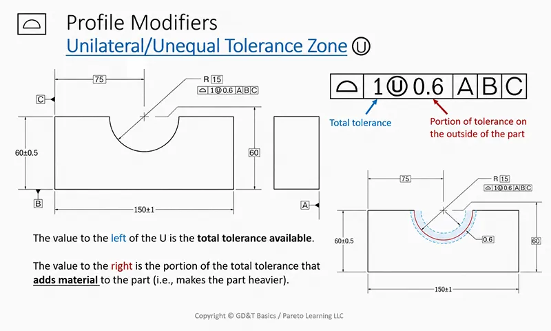
- Use GD&T and datums for complex controls: If multiple features must align or the part has complex geometry, a proper GD&T framework with datum references can control relations more effectively than simple size tolerances.
- Communicate clearly: Always include clear, explicit tolerances for critical dimensions. If a general tolerance standard applies (like ISO 2768), note it on the drawing. Label units and specify if a dimension is maximum material size (MMS) or least material size (LMS) where needed.
- Collaborate early: When in doubt, discuss with manufacturing and quality teams. They can advise on realistic tolerances and potential cost impacts. As one expert points out, tolerances should be set by functional requirements and manufacturing reality, not assumed by default.
By following these guidelines, you ensure that tolerances meet design intent without unnecessary cost.
Unilateral and Bilateral Tolerance in Engineering Drawings
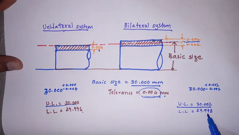
On engineering drawings, notation reflects the tolerance type. A bilateral tolerance is shown with a “±” sign, e.g. 20.00 ±0.05 mm means ±0.05 mm in both directions. A unilateral tolerance is written with asymmetric limits, such as 20.00 +0.05/−0.00 mm (only allowed to increase) or 20.00 +0.00/−0.05 mm (only allowed to decrease). In each unilateral callout, one side of the tolerance is set to 0.000.
Most CAD and drawing software handles this notation automatically. If many dimensions share the same baseline accuracy, a general tolerance note like ISO 2768 general tolerances may appear in the title block. Critical features, however, should be explicitly labeled with their specific tolerances (± or +/− values) rather than relying on a default. Always double-check that the drawing clearly indicates whether a tolerance is symmetric or one-sided, and that units and datum references are unambiguous.
Conclusion
In summary, unilateral and bilateral tolerances are two common methods of defining dimensional variation on engineering drawings. A unilateral tolerance restricts variation to one side of the nominal size, which is vital for function-critical features (e.g. ensuring a shaft never gets too large or a hole never gets too small). A bilateral tolerance allows symmetric (or asymmetric) variation on both sides of the nominal, and is widely used for general, non-critical dimensions.
Choosing between them is a design decision driven by each feature’s role in the product. Properly applied, tolerances ensure parts will assemble and function while controlling manufacturing cost. Tight tolerances improve accuracy but require more precise machining and inspection, often at exponential cost increase. Conversely, overly loose tolerances can result in assemblies that bind or wear out early. Therefore, engineers should base tolerance decisions on functional requirements and manufacturing capability. For CNC-machined parts, realistic tolerances lead to better quality and cost-effectiveness. Remember: the “best” tolerance is the one that ensures the part works without driving unnecessary manufacturing expense.
FAQ About Unilateral and Bilateral Tolerance
What is unilateral tolerance?
Unilateral tolerance allows dimensional variation only in one direction from the nominal. For example, a callout of +0.00/−0.10 mm means the part can only be smaller (up to −0.10 mm) and not larger than the nominal size. It fixes one side of the tolerance zone at zero so the dimension only deviates on one side.
What is bilateral tolerance?
Bilateral tolerance allows variation in both directions around the nominal dimension. It is usually written with a ± symbol. For example, 10.00 ±0.05 mm means the feature can be 9.95–10.05 mm. The tolerance zone is centered on the nominal size, so the part may be either slightly larger or smaller within that range.
What is the main difference between unilateral and bilateral tolerance?
The key difference is the direction of allowed variation. Unilateral tolerance is one-sided (e.g. +0.05/−0.00), meaning deviation is permitted only above or only below the nominal. Bilateral tolerance is two-sided (e.g. ±0.05), permitting deviation both above and below the nominal. In short, unilateral fixes one boundary at the nominal, bilateral does not.
Which tolerance is better for CNC machining?
Neither is inherently better; it depends on the feature. Unilateral tolerance is preferable for critical fits or one-sided functional limits (e.g. bearing bores, press fits), because it focuses control on the needed side. Bilateral tolerance is simpler for general features with no strict one-sided limit. In practice, fit-critical mating parts often use unilateral tolerances, while ordinary dimensions use symmetric ± tolerances.
Why do tolerances affect machining cost?
Tighter tolerances require more precise machining, special tooling, slower feeds, and additional inspection, which raises cost. As one analysis notes, defaulting to tighter tolerances can significantly increase manufacturing costs and lead time without adding functional value. Every increment of precision often requires more machining time and higher scrap rates. In short, a tighter tolerance means more work to achieve that precision.

