
Engineering drawing is the precise, standardized language that connects design, manufacturing, and quality inspection. In other words, a clear engineering drawing tells machinists exactly how to make a part — its size, shape, features, materials, and tolerances. For example, consider an engineer’s hand drafting a blueprint: every line and symbol on that page specifies a real-world requirement. According to industry sources, an engineering drawing “conveys information about an object,” commonly by specifying the necessary geometry for building components and assemblies. The drawing is often the master document linking detail part drawings and assembly drawings, with a title block that notes who created and approved it, the units and scales, revision history, and other metadata.
In short, engineering drawings are not sketches or illustrations. They use standardized views, dimensioning, symbols, and notes to remove guesswork. Unlike a freehand concept sketch, an engineering drawing shows orthographic (front, top, side, etc.) views at scale, with exact measurements and tolerances. It becomes the common language between designers, machinists, and inspectors: everyone who reads the drawing should “get clear instructions for making or fixing things,” with no ambiguity. This article walks through the key concepts: what an engineering drawing is, why it’s crucial for manufacturing, its types and elements, standards, and best practices. Real-world examples (from CNC shops to assembly lines) will illustrate why good drawings save time and money, and how to avoid common pitfalls.
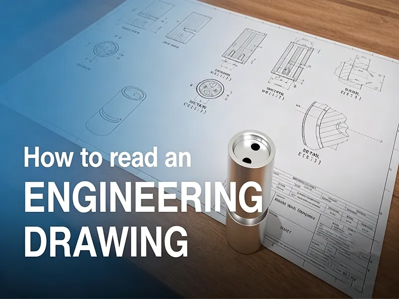
What Is Engineering Drawing?
An engineering drawing is a type of technical drawing that fully defines a part or system. It specifies the exact geometry, dimensions, and features needed to fabricate and inspect the part. In practice, you’ll see multiple views (front, top, side, etc.) that show all visible and hidden details. For instance, [26†embed_image] shows a traditional mechanical part drawing: you can tell hole sizes, slot positions, and overall shape at a glance, because it uses standard projection and dimensioning.
Engineering drawing vs sketch: a rough sketch might capture an idea, but it lacks precision. A true engineering drawing is drawn to scale, uses exact dimensions, and follows strict rules (per ISO or ASME standards) so anyone anywhere can interpret it the same way. For example, the Wikipedia definition emphasizes that engineering drawings use “pictographic representations” and standardized symbols/abbreviations to convey only the information needed. In other words, each measurement is shown only once to avoid inconsistency, and tolerances are specified to ensure the part will fit and function. Thus, an engineering drawing becomes the definitive blueprint: a manufacturing or inspection engineer doesn’t have to guess the intent because every detail is documented.
Why Engineering Drawing Is Important in Manufacturing
Good engineering drawings dramatically improve efficiency and quality on the shop floor. They reduce errors and rework by giving exact instructions to operators and machinists. As one industry guide puts it, detailed drawings “help you avoid errors and expensive fixes”. For instance, clearly dimensioned hole patterns and tolerances mean the CNC machine cuts parts right the first time. Missing or unclear dimensions, on the other hand, are a common source of scrap parts. In practice, machinists rely on drawings to communicate design intent: if the drawing shows a thread note with full details, or a GD&T symbol for a critical feature, the shop knows exactly what precision is needed. This clarity prevents the kind of costly mismatch that happens when a part “does not fit” or fails inspection later.
Engineering drawings also streamline communication between design and production teams. By providing a common reference, drawings cut down on back-and-forth questions. For example, a detailed assembly drawing will show how every component fits, which saves time when fabricating sheet-metal panels or welding frames. Inspectors likewise use the drawing to check if the finished part matches specifications. A title block and revision on the drawing ensure everyone is working off the latest design. In regulated industries (aerospace, medical, automotive), a drawing often serves as a legal record of what was built, supporting traceability and quality audits.
Practically, the impact is seen everywhere: in a CNC shop, the machine code is often derived directly from CAD models aligned with the drawing. In sheet-metal fab, a flat pattern drawing with bend notes keeps the process accurate. During final assembly, workers check off fits and finishes according to the drawing. In sum, a well-crafted engineering drawing prevents wasted material, minimizes guesswork, and keeps production on schedule. As one blog puts it, standardized drawing practices allow “drawing information to be interpreted properly, reducing guesswork throughout the manufacturing process”.
Main Types of Engineering Drawings
Engineering drawings come in a few standard categories, each serving a different role in design and production:
- Detail Drawings – Also called part drawings. They show a single component with complete dimensions, tolerances, material, and finish notes. A detail drawing is like the part’s recipe: it lists every cutout, hole, radius, and surface requirement. For example, a detail drawing for a steel bracket would include all edge dimensions, hole locations, surface roughness, and the material spec (e.g. “Steel 1018 per ASTM A108”).
- Assembly Drawings – These show how parts fit together into a final product. Assembly drawings illustrate part relationships: what goes where, how parts align, and what fasteners or welds join them. A classic example is an exploded-view drawing, where components are shown slightly separated along an axis to highlight the order of assembly. Such drawings often include a parts list (BOM) with quantities and item numbers. Assembly drawings ensure that the fabricator or maintenance team understands the full context.
- Sectional Drawings – Sometimes parts have internal features (pockets, ribs, hidden channels) that can’t be seen from the outside. A sectional drawing (e.g. a full section or half section) cuts the object along a plane to reveal interior details. Hatching lines indicate where material has been “cut away.” For instance, [28†embed_image] shows a sectional view of a curved staircase design, where the cut reveals structural supports inside the wall. Similarly, a section view of a gearbox housing would show the inside cavity for gears. Section views are invaluable for clarity — they show hidden features without crowding the main views.
- Exploded View Drawings – These are a type of assembly drawing where parts are drawn apart, like disassembled, to illustrate how they fit together. You often see exploded views in product manuals or maintenance guides. For example, a printer manual might use an exploded diagram to show each gear and circuit board location. The exploded view makes it easy to see each component and its orientation, improving assembly accuracy.
- Schematics and Diagram Drawings – Not all engineering drawings show mechanical parts. Schematics (electrical diagrams, piping layouts, pneumatic/hydraulic systems) convey systems-level relationships. A wiring schematic, for instance, shows how circuits connect with symbols for switches and resistors. While schematics follow different conventions from mechanical drawings, they serve the same purpose of clear, standardized communication. They differ from mechanical drawings in that they emphasize functional flow (current, fluid, etc.) rather than physical shape and dimensions.
Key Elements of an Engineering Drawing

A complete engineering drawing contains several consistent elements that convey all needed information:
- Title Block – Usually found at the bottom or lower-right corner. It includes the drawing title (part name), drawing number, revision, scale, and units. It also lists the drafter’s name, checker/approver, and date. The title block might include general notes or reference standards. For example, per standard practice, the title block might read: “Widget Base, DWG-1234, Rev. B, 1:2 scale, units in mm. Drawn by A. Engineer, Checked by B. Inspector.” This metadata ensures there’s no confusion about which version of the drawing everyone is using.
- Dimensions – These are the core information. Dimensions specify lengths, widths, heights, angles, radii, hole sizes, etc. Linear dimensions (between two points), angular dimensions, and diameter/radius symbols (Ø for diameter, R for radius) are used. Clear, unambiguous dimensioning is critical. For instance, a shaft might be dimensioned “Ø10.00 ±0.02 mm” indicating its precise diameter and tolerance. In practice, you should avoid placing the same dimension on multiple views (no redundant or conflicting dimensions). The rule is: every necessary dimension appears exactly once on the drawing to prevent errors. Good dimensioning also follows a logical order: larger overall sizes outside, finer features closer to the part outline. This hierarchy helps machinists read the drawing without confusion.
- Tolerances – These define the allowable variation for a dimension. There are usually two levels: general tolerances (applied to all dimensions without an explicit tolerance) and specific tolerances listed next to critical dimensions. Tolerances ensure parts fit and function. For example, a width might be 50.00 +0.05/–0.02 mm, meaning the actual part can be as small as 49.98 or as large as 50.05 mm. Engineering drawings often specify tolerance classes (e.g. fit and allowance for mating parts) or reference standards (like ISO fits). Tolerances matter because they balance manufacturing cost and function: tighter tolerances mean higher precision and cost, while loose tolerances risk poor fit. Properly specified tolerances ensure production consistency and correct assembly fit.
- Lines and Line Types – Lines carry meaning in drawings. Solid (continuous) thick lines are for visible edges. Dashed lines represent hidden edges or holes behind surfaces. Center lines (alternating long and short dashes) mark axes of symmetry or hole centers. Cutting-plane lines (wide dashed) show where a section is taken. Dimension and extension lines use thinner strokes to call out measurements. Using the correct line style (per ISO 128 or ASME Y14.2 standards) is important to avoid confusion. For example, if a centerline is drawn incorrectly, a machinist might mislocate a hole. In practice, you’ll often see a legend or note explaining line types, but at a minimum the basic conventions must be followed so drawings are easily interpreted by any engineer.
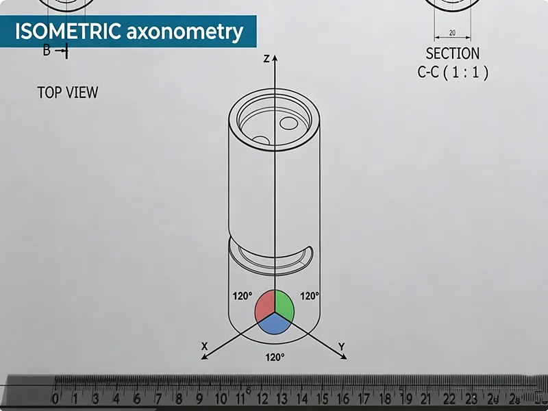
- Views – These are the different perspectives of the part. The main views are typically front (primary view), top, and side. An orthographic projection lays out 2D views that collectively show the 3D shape. In addition, drawings may include an auxiliary view (to show an angled face in true size), or an isometric view which is a 3D-like sketch. Isometric drawings (like [27†embed_image]) are often used as visual aids but are not dimensioned – they help the reader visualize the part. Most manufacturing-critical information comes from the orthographic views. A note of caution: ensure you specify the projection method (first-angle or third-angle), since the orientation of views differs by region (ISO uses first-angle, ASME/ANSI uses third-angle). Without this, a top view could be interpreted on the wrong side of the front view.
- Symbols – Specialized symbols convey standard information compactly. Common symbols include: diameter (Ø) and radius (R) for circular features, countersink (⌴) and counterbore (⌵) for special hole ends, and thread notation (e.g. “M6×1.0”) for screw threads. There are also surface finish symbols (a checkmark-like symbol indicating roughness requirements), welding symbols (for where and how parts are joined), and GD&T symbols (in feature control frames) for geometric tolerances. Each symbol means the same thing universally. For example, a square with arrows is the symbol for flatness, a circle with a line is for true position, etc. These allow an engineer to specify complex requirements (like “hole must lie within 0.1 mm of true position relative to datums A and B”) in a small notation.
- Notes and Annotations – In addition to dimensions and symbols, drawings often contain notes. These might specify material (e.g. “Material: 6061-T6 Aluminum per ASTM B209”), finish (e.g. “Hardcoat anodize 0.002””), or other processing instructions (“Remove all sharp edges 0.5 mm R”). Such notes ensure manufacturing knows exactly what to do. For example, a note might say “heat treat to 50-55 HRC after machining,” or “deburr all holes.” These annotations bridge any information not easily captured by symbols. It’s common to have a general note stating the default tolerance (e.g. “Unless otherwise specified, dimensions ±0.1 mm”).
By combining all these elements, an engineering drawing becomes a complete instruction set. It leaves very little to chance. In fact, one key principle of engineering drawing is clarity: it must be unambiguous and readable. An unclear or cluttered drawing can lead to expensive mistakes. Standards exist (ISO, ASME) to keep drawings consistent and avoid misinterpretation.
Basic Principles of Engineering Drawing
All engineering drawings should adhere to five basic principles: clarity, accuracy, completeness, consistency, and readability.
- Clarity – Every line, symbol, and note must be legible and unambiguous. Crowding too many dimensions can clutter a view; using proper line types prevents confusion. Ambiguity is the enemy of production – if a machinist is unsure which dimension applies, it causes delays or errors. In practice, clarity means organizing views and notes so that they are easy to follow.
- Accuracy – The drawing must correctly reflect the design. A mis-labeled dimension or wrong symbol undermines the entire build. Accuracy ties back to the chosen standards and to correct calculations (e.g., using an accurate scale, verifying dimension math, etc.).
- Completeness – All information needed to make and inspect the part must be present. The drawing should not assume unstated conventions. As a general guideline from NASA’s engineering drawing standards says: “Complete drawings contain or make reference to all data necessary for fabricating and installing the part”. This includes every critical dimension and tolerance, as well as material and finish. If a detail is missing, someone must ask, causing delays.
- Consistency – Use uniform symbols and standards throughout. For example, if one detail uses first-angle projection symbols and another uses third-angle, the drawing set becomes inconsistent and potentially unreadable. Date and revision conventions, dimensioning style (e.g. decimal places, plus-minus or limit), and even text fonts should follow one standard. This consistency is enforced by adhering to recognized engineering standards (ISO 128/ASME Y14 series etc.) and company drawing guidelines.
- Readability – Layout the drawing so that it can be quickly understood. Short, purposeful notes; logical dimension placement; and sensible grouping of related features all improve readability. Drawings may include reference letters or numbers to tie notes to features. In practice, good readability means a machinist can take one look and know where to measure. Tools like CAD software layers also help maintain readability when drawings are complex.
In short, avoid ambiguity at all costs. Every person who reads the drawing—be they a machinist, welder, or quality inspector—must come to the same understanding. Inconsistent or incomplete drawings are a common source of “drawing errors” that cost time and money.
Engineering Drawing Standards and Conventions
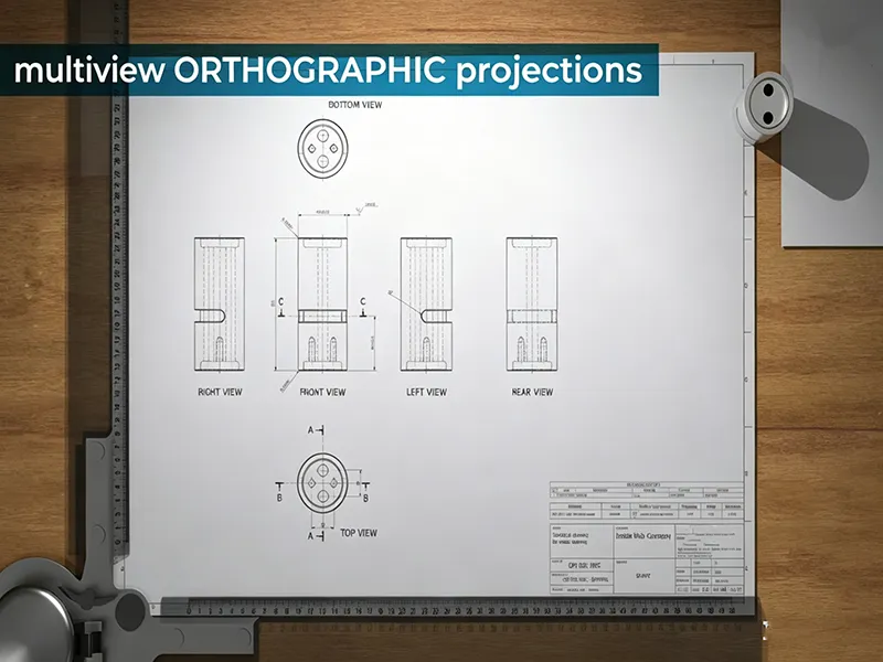
To maintain the principles above, engineers follow international standards and conventions:
- ISO Standards – The International Organization for Standardization publishes many relevant documents. For example, ISO 128 covers general presentation of drawings, ISO 5455 defines scales, and ISO 1101 is the global standard for geometric tolerances. Most countries outside the U.S. use ISO standards by default. These standards cover everything from line thicknesses to symbol shapes.
- ASME/ANSI Standards – In the U.S., ASME Y14 series provides similar rules. For instance, ASME Y14.5 (current version 2018) is the authoritative guide for dimensioning and tolerancing, including GD&T. ASME Y14.2 covers line conventions, Y14.3 is multiview projections, Y14.24 is types and applications of engineering drawings, and so on. Companies often mandate following either ISO or ASME, or both.
- Third-Angle vs First-Angle Projection – One of the most visible differences between ISO and ASME conventions is projection. In first-angle projection (ISO), the object is placed behind the plane, so the top view is drawn below the front view, and the right-side view is drawn on the left. In third-angle projection (ASME), the object is between the observer and the plane, so the top view is above the front view (and the right view is on the right). The drawing should always indicate which convention is used (often with a symbol in the title block) to prevent mis-interpretation. North American drawings almost always use third-angle; European and other regions use first-angle.
- Consistent Units and Formats – The drawing must indicate whether dimensions are in inches, millimeters, etc., and whether decimals or fractions are used. Often a note in the title block sets the unit system (for example “Dimensions in millimeters unless noted”). This avoids unit conversion errors (which can be disastrous).
By following these standards, engineering drawings from different companies or countries stay consistent. For example, a German engineer reading a Japanese drawing will interpret the same symbols under ISO. Similarly, factories in the U.S. rely on ASME standards to align design and production expectations. In practice, the standards reduce confusion: they establish the “grammar” of the drawing language, so focus can stay on the design itself.
Understanding Views in Engineering Drawing
Here’s how the different views function in practice:
- Orthographic Projection (Multiview) – This is the bread-and-butter of engineering drawings. Typically, you’d see a front view (showing height and width), a top view (width and depth), and a side view (depth and height). These are true-scale views with no distortion. In manufacturing, orthographic views are used for precise dimensioning and are generally what CNC programs and inspection reports are based on. The advantage is that any point or edge can be measured directly.
- Isometric Drawing – Sometimes a drawing includes an isometric (3D-like) view for clarity. [27†embed_image] shows an isometric CAD view of a mechanical part on a screen. Note that isometric views are not dimensioned, because they are not to scale in every axis. Instead, they help readers visualize the part’s shape at a glance. Isometrics are valuable when communicating with non-technical stakeholders or in patents and presentations, but the official dimensions always come from the orthographic views.
- Section Views – As mentioned, section (cutaway) views reveal hidden interior details. There are different types: a full section cuts entirely through, a half section removes one-quarter of the object to show interior on one side, and a broken-out section cuts only a small portion. For example, a half section of a gearbox would show one half of the housing removed, exposing the gears inside. This level of detail is critical when an internal feature (like a keyway or internal thread) must be machined or inspected.
- Detail Views – When a particular area of a part is very complex or small, the drawing may include an enlarged detail view. This is a zoomed-in view of a feature, often with its own callouts. For instance, a small precision hole in an engine block might be too detailed in the context of the full drawing, so the drawer creates a detail A view 2:1 scale just for that area. These views improve readability by showing fine details without cluttering the main view.
In practice, creating effective views is both an art and a science. The engineer must choose enough views to completely define the part, but avoid unnecessary duplicates. Additional views are only added if a feature cannot be clearly dimensioned otherwise. The drafting standard ASME Y14.3 gives rules on placing views.
Common Symbols Used in Engineering Drawing
Here are some of the ubiquitous symbols you will see:
- Diameter (Ø): Placed before a number (e.g. Ø10) to indicate a circle’s diameter. Without it, a number by a circle might be interpreted as a radius or chord length, so the symbol is essential.
- Radius (R): Similarly, “R5” means a radius of 5 units. It’s typically used for fillets or round corners.
- Countersink (⌴) and Counterbore (⌴ with a flat bottom): Indicate that a hole has a conical recess (for a screw head) or a flat recess. These symbols appear next to hole dimensions (e.g. “⌴0.25×90°” means a 0.25″ diameter countersink at 90 degrees).
- Thread: Threads are often called out with text (like “M8×1.25–6g”), but sometimes a triangular thread symbol is used on the drawing. The note will specify standard (e.g. “UNC” or “ISO Metric”) and depth.
- Surface Roughness (Ra): A small checkmark-like symbol indicates machining finish requirements. Numbers (like 1.6) may accompany it to specify roughness in micrometers.
- Datum Symbol (letter in a square or triangle): Used in GD&T to identify reference surfaces (e.g. “A”, “B”, “C”). These tell the inspector which face or axis is the primary reference for measurements.
- GD&T Symbols (□, ⌀, ⊥, //, etc.): These appear inside rectangular feature control frames. For example, a frame might contain “⊥|0.1|A|B|” indicating a perpendicularity tolerance of 0.1 relative to datums A and B. (Common GD&T symbols include Position, Flatness, Straightness, Perpendicularity, Parallelism, Circularity, etc.). Each symbol’s meaning is defined by the ASME or ISO standards.
A key rule is that symbols are read the same way by anyone. For example, a slot might be labeled “10×5” with a slot symbol, which is universally understood to mean a 10×5 slot (the slot symbol itself can vary by standard). Using standardized symbols keeps text minimal and avoids language barriers.
Dimensioning in Engineering Drawing
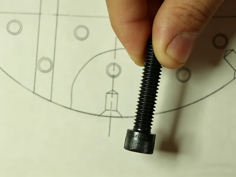
Dimensioning must follow clear rules:
- General Guidelines: Place dimensions outside the object’s outline whenever possible, with extension lines pointing to the feature. Use arrowheads or tick marks to show dimension extents. Always indicate the unit (mm, inches) or specify them in a note. Double-check that all necessary dims are present and none are duplicated. (For example, do not dimension the width in both the front and top views – that would be redundant.)
- Baseline (Datum) Dimensioning: This method measures features from a common reference line. For example, all hole centers might be measured from the left edge of a plate. This avoids cumulative error because each hole position is independent. In technical terms, baseline dimensioning sets a “datum line” for each axis, and all dimensions are taken from it. This is often preferred for precision parts.
- Chain Dimensioning: An older method where each feature is measured from the previous one (A to B to C). This can lead to tolerance stack-up (errors accumulate along the chain). For example, if three holes are each dimensioned 10.00 mm apart in a chain, the last hole could be off by the sum of all tolerances. Baseline dimensioning is generally safer when tight tolerances are critical.
- Avoid Over-Dimensioning: Only include dimensions that are necessary for manufacturing. Too many dimensions crowd the drawing and risk inconsistency. For instance, if you show the overall height of a block, you usually don’t need to show it again broken into pieces in the same view. Key features that control fit or function should be dimensioned; non-critical details might just be implicit from the geometry or a note.
- Ordinate Dimensioning: A variation of baseline dimensioning often used in CNC programming. Features are assigned coordinates (ordinates) along axes. It’s somewhat like baseline dimensioning and is useful for fully defining geometry without chaining.
In short, dimensioning should be systematic and logical. The goal is that a machinist can pick up the drawing and identify each critical measurement with a ruler or a coordinate machine. Clear hierarchy (larger dims outside, smaller dims inside) and avoiding dimension lines crossing each other are practical tips for readability.
Tolerances and GD&T in Engineering Drawing
Why Tolerances Matter
Every manufacturing process has variability: drills wander slightly, tool wear grows, and temperatures change. Tolerances define how much variation is acceptable. Tight tolerances (small variation) ensure high precision but increase cost; loose tolerances save money but risk poor fit. For example, doubling a tolerance band (making it twice as tight) can roughly double manufacturing costs due to more rejects and finer tools. Conversely, overly loose tolerances may mean parts rattle or leak.
In assemblies, tolerances govern how parts fit together (clearance vs interference fits). For instance, a shaft and hole may require a specific clearance to spin freely or to press-fit. Without proper tolerancing, one lot of parts might fit and the next might not. Thus, tolerances are essential for production consistency and cost control. As one guide notes, GD&T was originally driven by wartime needs to save time and material while ensuring parts could still assemble reliably.
Basic GD&T Concepts
Geometric Dimensioning and Tolerancing (GD&T) is an advanced system to precisely describe allowable variation in form and position:
- Datum: A theoretical reference point, line, or plane used as a starting point for dimensions. For example, Datum A might be the flat base of a part. All positional tolerances are then relative to these datums.
- Feature Control Frame: The rectangular box that contains a GD&T specification: it has compartments for the symbol (e.g. ⌀ for position, ⊥ for perpendicularity), the tolerance value, and references to datums. For instance, a frame might read “⊥ | 0.05 | A | B” meaning perpendicularity within 0.05 mm of datums A and B.
- Position: (Symbol: ⌀) Controls the location of a feature (like a hole) relative to datums. It’s one of the most common controls for hole patterns.
- Flatness: (Symbol: ▬) Ensures a surface is within two parallel planes a certain distance apart. Used for surfaces that must seal or mate.
- Perpendicularity/Parallelism: (Symbols: ⊥, ∥) Control the 90° or 0° relationship between surfaces or axes. For example, ensuring a bracket’s mounting face is perpendicular to its base.
- Profile: (Symbol: ⌵ profile of a line or ◯ profile of a surface) Controls complex curved shapes’ tolerance, often used in aero surfaces.
- Flatness/Circularity/Cylindricity: Control form deviations (how “flat” or “round” a feature is along its length).
GD&T essentially allows specifying a functional tolerance zone. For example, instead of saying “hole is within a 0.1 mm square in X-Y,” GD&T position can define a circular zone that often better matches how the part functions. It can also decouple tolerances: you might allow a hole to move slightly (position tolerance) without tightening its diameter tolerance, or control angularity relative to surfaces rather than coordinate axes. The ultimate benefit is clearer communication of design intent and often lower cost, because GD&T tells the manufacturer and inspector exactly what matters for part function.
GD&T vs Traditional Dimensioning
Traditional (coordinate) dimensioning specifies size and location via plus/minus tolerances. While simpler, it can lead to ambiguity in complex parts. For example, if a hole is dimensioned 10.00±0.05 at certain coordinates, its true position tolerance might be unclear. GD&T solves this by explicitly linking the hole’s allowable deviation to functional references (datums). As one engineer notes, GD&T describes the “design intent rather than the resulting geometry”. In other words, GD&T tells the manufacturer what the part must do (e.g. fit, seal, roll) instead of just what shape it must be. This reduces unnecessary tight tolerances: if a hole’s exact position isn’t critical to the part’s use, GD&T can allow more leeway there and tighten only what truly matters. Overall, GD&T provides a standardized, concise way to control complex tolerances, which traditional methods struggled to handle without creating overly conservative specs.
Materials and Surface Finish Information on Drawings
Engineering drawings usually include notes on material and finishing, because these affect manufacturing and performance:
- Material Callout: It should specify the exact material grade and any standards. For example: “Aluminum 6061-T6 per AMS-QQ-A-250/11”. This tells the shop the alloy, temper, and spec sheet. The material choice affects machining parameters and part behavior (strength, corrosion resistance, etc.). As one guide emphasizes, simply writing “steel” is not enough – a grade and spec are needed to ensure the right alloy is used.
- Heat Treatment Notes: If the part needs post-machining hardening or stress relief, that is noted (e.g. “Heat treat to 50-55 HRC per AMS 2759, then temper”).
- Coating/Plating: Any surface coating (anodizing, plating, painting) should be specified with thickness and spec. For example “Hard Chrome Plating, thickness 0.02 mm minimum per MIL-C-83486”. These requirements impact dimensions (the plating adds thickness) and are critical for durability or corrosion resistance.
- Surface Roughness/Fit: Symbols or notes indicate how smooth a surface must be. A bearing surface might require Ra 0.8 µm, whereas a non-critical face could allow Ra 3.2 µm. Surface finish affects functionality and cost.
- Bend or Grain Information (for sheet metal): If the grain direction or bend allowance matters, it may be annotated (e.g. “Grain parallel to A-B edge”).
These notes matter because they ensure the part’s material properties match its intended use. A wrong alloy or missing heat treatment could cause failure. Moreover, machinists use this info for quotes: harder materials mean slower feeds and more wear, which raises cost. Specifying the material early helps the manufacturer plan accordingly. In practice, the title block or a corner note often includes a “material” and “finish” line to capture all these details.
How to Read an Engineering Drawing Step by Step
For someone new to reading drawings, a systematic approach helps:
- Start with the Title Block. Note the part name, scale, units, revision, and any general notes. Make sure you have the latest revision.
- Look at the Main Views. Identify the front view and then the corresponding top/side views. Get the overall shape and dimensions. Sketch a quick mental 3D picture if it helps.
- Check Dimensions and Tolerances. Go through each view and note the critical dimensions (especially overall size and hole locations). Pay close attention to any tight tolerances or GD&T symbols. These indicate critical features. Confirm that dimensions add up (no obvious math mistakes or missing values).
- Read All Notes and Symbols. Examine any callouts, material notes, surface finish symbols, and datums. For example, if a hole is labeled “M8x1.25-6H”, recognize it as a metric thread callout with class 6H tolerance. Check the title block for the default tolerance values if some dims lack explicit tolerance.
- Verify Material and Finish. The notes should specify the material and any treatments. Confirm these align with what you expect for the part’s application.
- Understand Assembly Context (if assembly drawing). If it’s an assembly, find the parts list and see how each part is located (often with reference designators). Ensure mating parts have compatible tolerances (fits, thread notes, etc.).
This process – from title block to detailed features – ensures you don’t miss anything. It’s the same workflow used by quality inspectors when checking a part. Taking the drawing one section at a time prevents errors that come from skipping around.
Common Mistakes in Engineering Drawings
Even experienced engineers can slip up. Some frequent mistakes include:
- Missing Dimensions: Forgetting to dimension a feature means nobody knows its size. For example, leaving out the depth of a hole or the radius of a fillet.
- Over-Dimensioning: Adding unnecessary duplicate dimensions that clutter the drawing and can conflict. For instance, dimensioning the width of a part in both the front and top views.
- Unclear Tolerances: Not specifying tolerances for critical features. If a dimension has no tolerance, people fall back on the title block defaults (which may be too loose or too tight). We saw above that missing tolerance on a critical size can lead to wrong parts.
- Wrong Projection Method: Mixing up first-angle vs third-angle by accident is a classic issue, especially in international projects. This can flip the arrangement of views. Always check the projection symbol in the title block to avoid this.
- Inconsistent Symbols: Using a symbol one way on one view and differently on another, or using non-standard symbols. Standard practice and consistency eliminate guesswork.
- Incomplete Notes: Not calling out the material correctly (“aluminum” vs “6061-T6 aluminum”), or leaving out surface finish info. One guideline bluntly notes missing a material spec is a top error.
- Revision Control Mistakes: Sending an outdated drawing without updating the revision block. This can be disastrous if a part was changed after release. Always update the revision letter and date for any drawing change.
Catch these errors by thorough review. Many companies do a drawing check where a second engineer verifies every dimension and note. The checklist usually covers the above points (and more).
How Engineering Drawings Are Used in Modern Manufacturing
Today’s factories are high-tech, but engineering drawings remain the backbone. Here’s how they fit into common processes:
- CNC Machining: Drawings guide CAM programming. The machinist or CAM engineer inputs the dimensions and hole locations directly. GD&T callouts can translate into features in the CAD/CAM model. When a CNC machine is running, it’s effectively following a digital interpretation of the drawing. Also, coordinate measuring machines (CMMs) use the drawing’s dimensions and datums to verify parts.
- Sheet Metal Fabrication: Flat patterns and bend drawings come with bend lines and angles. Drawings specify where to cut, bend, or notch. The shop follows these drawings to form parts to exact shape. In assembly drawings, the tab-and-slot locations might be dimensioned to ensure welds align.
- Welding and Assembly: Weldment drawings show plate sizes, weld symbols, and assembly order. For example, a drawing might call out “Weld all edges full fillet 3 mm” on a bracket. Assemblers use exploded assembly drawings to place parts correctly. Bolt patterns and torque specifications may also come from the drawing’s notes.
- Tooling and Mold Making: Engineering drawings for molds or jigs are extremely precise, often with many GD&T annotations. The mold maker follows these to create the die that forms plastic or cast parts. The drawing ensures the final molded part will have the intended dimensions and surface finish.
- Quality Inspection: The quality team uses drawings as the gold standard. They measure completed parts against every dimension and tolerance on the drawing. Modern QA may use automated tools (like laser scanners or CMMs) that align to the CAD model derived from the drawing, but the drawing remains the documented authority on what is acceptable. Many companies link drawing information to inspection software for traceability.
In essence, engineering drawings underlie every manufacturing step. Even as factories use 3D CAD and digital twins, the 2D drawing often remains the legal contract and point of reference. For example, one manufacturer noted that even with full 3D digital models, “technical drawings help you keep records of your work” and ensure consistency.
Engineering Drawing vs CAD Models
3D CAD models and engineering drawings serve different but complementary roles:
- CAD Models: These are rich 3D representations. They are great for simulation, visualization, and automated process planning. A CAD file holds the full geometry and can easily be manipulated (rotated, sectioned). However, by themselves they may lack explicit annotations like dimensions or tolerances unless a drawing is derived. Also, sharing a CAD model assumes the recipient has compatible software and knows how to extract information.
- Engineering Drawings: They are concise, universally readable summaries of the necessary data. A drawing (print or PDF) can be viewed without special CAD tools. It shows the exact dimensions and manufacturing notes in human-readable form. Even if a 3D model exists, drawings are still needed for fabrication shops that operate in 2D space. In many industries, a drawing is the “legal document” that gets approved by engineering change control, not the CAD file.
In practice, firms use both. The CAD model is often the source for a drawing. But one cannot completely replace the other yet. For example, some tolerances and surface finish symbols cannot be captured directly in most CAD files. Furthermore, regulators and quality standards often require a 2D drawing for documentation. As one engineer notes, GD&T is defined in standards specifically for use on engineering drawings, models defined in digital data files, and related documents. That implies the drawing is part of the official documentation set, alongside the model.
Thus, the best practice is: create a detailed engineering drawing from your CAD model (or vice versa), ensure it is checked and controlled, and use it as the main reference in manufacturing. CAD aids design and analysis, but the drawing communicates the manufacturing recipe.
Tips for Creating Better Engineering Drawings
- Keep dimensions and notes concise. Only dimension what is necessary for function. Remove any redundant or obsolete dimensions before release.
- Follow a single standard consistently (either ISO or ASME as dictated by your company/region). This includes projection method, units, and symbol usage.
- Avoid ambiguity. For example, place dimensions clearly with no overlapping lines. Use leader lines to point at features. If needed, add a note like “all holes without location note are equally spaced.”
- Design for manufacturability. Before finalizing the drawing, consider the process. If a feature is too difficult or costly (like an extremely tight tolerance on a low-function area), relax it. Early collaboration with machinists or fabricators can catch such issues.
- Communicate with fabricators and inspectors. A short conversation about critical features can save confusion. For example, if a particular flatness is crucial, highlight it in a note or with a GD&T symbol. Those on the floor often spot issues that aren’t obvious on paper.
- Check revision control. Make sure each drawing has a revision letter or number that changes with each update. Update the date and the “revised by” fields so everyone knows they are using the latest version.
Following these practices makes drawings clearer and reduces the chance of errors on the shop floor. Good drawings empower manufacturers, rather than causing headaches.
Summary
In summary, engineering drawings are the lifeblood of mechanical design and manufacturing. An engineering drawing is a precise, standardized illustration that conveys all the information needed to produce a part or assembly. It’s the common language bridging design, fabrication, and inspection. Key elements of a drawing include the title block, clear dimensions, tolerances, proper views, and standardized symbols for features (like diameters, threads, and GD&T controls).
These drawings are vital in manufacturing: they reduce communication errors, ensure parts fit together, and guide quality control. Even in the age of 3D CAD and automation, 2D drawings remain indispensable because they document the exact specifications in a portable, unambiguous format. To read an engineering drawing, start by understanding the title block and views, then follow dimensions, tolerances, and notes. Consistent standards (ISO/ASME) ensure these documents are interpreted correctly worldwide.
Finally, keep drawings clear and to-the-point: avoid missing or conflicting dims, specify material and finish carefully, and make sure critical tolerances are spelled out. A well-crafted drawing saves time and money; a sloppy one can cost dearly in rework. By mastering these drawing principles, engineers and manufacturers can collaborate smoothly and produce high-quality parts efficiently.
FAQ
What is an engineering drawing?
An engineering drawing is a detailed technical plan for a part or system. It shows the shape and features of each component, with all required dimensions, materials, and notes needed for manufacturing and inspection.
What are the key elements of an engineering drawing?
The key elements include: the title block (with part name, drawing number, revision, scale, etc.), dimensions (linear, angular, hole sizes), tolerances (allowable variations), views (front/top/side/sections), lines (visible, hidden, center), symbols (e.g. diameter Ø, countersink, surface finish, GD&T), and notes/annotations (material, finish, special instructions). Each element conveys specific information needed to build the part.
Why is engineering drawing important in manufacturing?
Engineering drawings ensure that what the designer intends is exactly what the factory produces. They improve communication between engineering and production, reduce errors and rework, and provide a precise checklist for quality control. In essence, they turn an idea into a manufacturable reality.
What is the difference between first-angle and third-angle projection?
These are two different ways to arrange views on a drawing. In first-angle (used in Europe/ISO), the top view is placed below the front view, and the right side view is on the left of the front view. In third-angle (used in North America/ASME), the top view is above the front view, and the right side view is on the right. The projection symbol on the drawing indicates which method is used.
How do you read an engineering drawing?
Start with the title block to get context (part name, scale, etc.). Then examine the main orthographic views to understand the overall shape. Check each dimension and tolerance carefully. Read any notes or symbols for material, finish, or special requirements. Finally, visualize or check each view matches the others. A systematic pass (top-to-bottom, view-by-view) helps ensure no detail is missed.
What is the role of tolerances in engineering drawing?
Tolerances specify how much a part can deviate from the nominal dimensions. They are critical for ensuring parts fit together and function properly. Tight tolerances mean higher precision (and cost), while looser tolerances reduce cost but must still meet functional needs. GD&T provides a structured way to define these tolerances relative to datums, focusing on function (assembly fit, part performance) rather than just raw dimensions.

