
CUSTOM DRONE PARTS · BUYER’S GUIDE
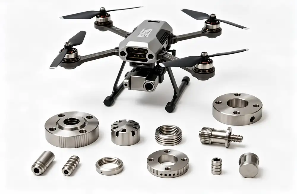
Common CNC-machined drone parts include motor mounts, arm clamps, frame connectors, gimbal brackets, electronics housings, and propeller adapters. These components can require accurately located mounting holes, controlled mating surfaces, or custom geometry.
The right manufacturing method depends on the material, part design, production quantity, and application requirements. This guide focuses on custom metal drone and UAV components, explaining where CNC machining is used and what buyers should specify before requesting a quote. Not every drone component needs to be machined from metal.
IN THIS GUIDE
Motor mounts and adapters · Arm and frame connections · Gimbal and camera mounts · Housings and heat sinks · Landing gear and fittings · What to include in your RFQ · Request a Quote · FAQs
Motor Mounts, Motor Housings, and Propeller Adapters
Motor mounts connect a motor to an arm or frame. Machined features may include a mounting face, bolt pattern, locating features, and the interface to the supporting structure. Buyers should identify which holes locate the motor and which provide fastener clearance. Specify the relationship between these features where it matters for assembly, and include the mating motor drawing when available.
Motor housings and end covers are mechanical components with requirements separate from windings and control electronics. Depending on the design, machining may create internal fitting locations, end faces, mounting flanges, or threaded fastener interfaces. Identify the surfaces that support or locate mating components, rather than applying the same tolerance to every dimension. State whether any fits must be accepted after surface treatment.
Propeller adapters and hubs connect the propeller assembly to its shaft or mounting interface; they are distinct from complete propeller blades. A useful drawing defines the shaft bore, attachment method, relevant shoulders, and critical dimensions. Where the project requires checks for runout, concentric relationships, or balance, specify the acceptance criteria and inspection scope. CNC machining alone does not establish vibration performance for the assembled propulsion system.
For your RFQ: Include mating interface drawings, the material specification, prototype quantity, and expected production quantity. Identify any interface details that still require discussion before manufacture.
Arm Clamps, Frame Connectors, and Folding Joints
A drone can use machined metal connectors alongside composite arms or frame panels. Arm clamps secure a tube or other arm section; connector blocks join structural members; folding joints and hinge seats provide interfaces for moving assemblies. Their requirements depend on the parts they connect, not simply on the outside shape of the metal component.
For a tube clamp, provide the mating tube dimensions and relevant dimensional variation, together with the fastening arrangement. For a frame connector, identify the assembly reference surfaces and hole locations. A folding joint drawing should show the mating hinge or pin interface and any agreed assembly clearances. If a feature must be checked in an assembled condition, explain that condition.
Include the current drawing revision and an assembly view where separate part drawings leave the fit unclear. Specify surface treatment and any areas that require masking or dimensional control after finishing. This information helps the supplier assess the actual interface. Load capacity, clamping performance, and service life remain design and validation requirements for the project, rather than outcomes established by a quotation.
Gimbal Brackets and Camera Mounts
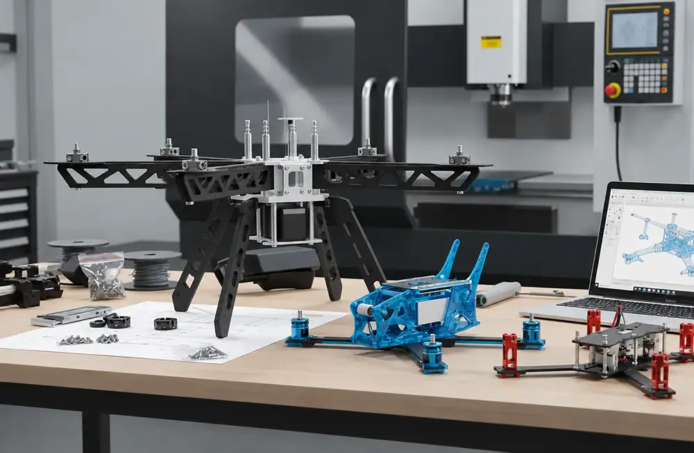
Gimbal brackets, camera mounting plates, and sensor mounts can provide custom interfaces for civilian surveying and inspection equipment. Buyers should define mounting hole positions, mating faces, assembly clearances, and the dimensions that need inspection. An accurate bracket supports the intended assembly geometry, but image stability also depends on the wider gimbal and control system.
Example: A buyer supplies a camera bracket model without identifying its locating holes or assembly contact faces. Before confirming manufacture, the supplier needs to clarify which holes establish position, which accept fasteners, and which surfaces contact the camera or adjacent bracket. These distinctions can change machining and inspection requirements.
Submit the bracket drawing with the necessary camera or sensor interface information. Show the space available for installation, connector access, and fastener access where these affect the part. If appearance matters, mark the visible faces and define the desired finish, including any agreed cosmetic acceptance criteria. Separating appearance requirements from functional interfaces gives the supplier a clearer basis for reviewing both production and inspection.
Electronics Housings and Heat Sinks
Custom electronics housings, sensor enclosures, cover plates, heat spreading bases, and heat sinks may use CNC machining to create project-specific interfaces. For an enclosure, external length, width, and height are only part of the specification. Internal mounting positions, connector openings, cover alignment, and clearance around installed components also affect the design.
Provide a model showing internal features and a drawing that identifies critical opening locations and cover fits. Mark exposed cosmetic faces and specify the surface treatment. Where a gasket, electrical contact, or mating component creates additional interface requirements, document the relevant dimensions and acceptance conditions. Avoid relying on the supplier to infer them from the overall shape.
For heat sinks and thermal contact bases, define the material, mounting arrangement, contact surfaces, and applicable flatness or finish requirements. The project designer should establish operating conditions and validation methods for any thermal target. A machined aluminum housing does not, by itself, establish a waterproof rating, shielding effectiveness, or a specific cooling performance. Include the assembly or acceptance requirements that apply to your enclosure or thermal component.
Landing Gear Brackets and Precision Fittings
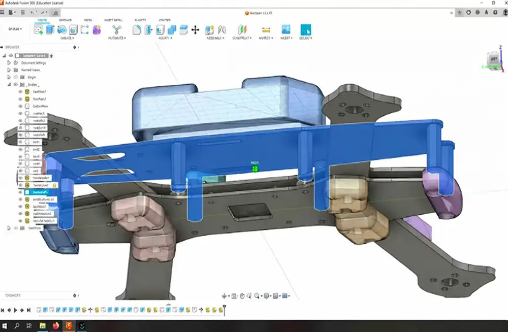
Other candidate components include landing gear mounting brackets, hinge fittings, and custom bushings. A bracket provides an attachment interface, while a hinge fitting or bushing can locate a mating pin or shaft. Whether machining is appropriate depends on the individual drawing and quantity.
Identify the connected components, dimension the mounting or fitting holes, and mark the positions that require inspection. If surface treatment affects a mating diameter or contact face, state whether the acceptance dimensions apply before or after finishing. Provide the target quantity and any required inspection documents. Where sample approval is part of the purchasing process, define what the sample must demonstrate and which drawing revision governs approval before releasing the next batch. This makes the transition from a trial assembly to repeat ordering clearer.
What to Specify Before Ordering CNC-Machined Drone Parts
Material Grade and Surface Finish
Specify the material grade and condition, rather than writing only “aluminum.” Identify the required 6061 or 7075 alloy and temper where applicable. The Aluminum Anodizers Council’s ordering guidelines highlight specifications such as alloy, coating thickness, color, and dimensional tolerances. Review the material and finishing options associated with CNC machining services, then confirm your part’s requirements, including any masking or appearance criteria. Select the material for the design instead of treating a more expensive alloy as an automatic upgrade.
Critical Fits, Tolerances, and Inspection
Identify dimensions that affect assembly and the features requiring particular inspection attention. ASME Y14.5 provides a common framework for communicating geometric tolerances and datum references. Choose CNC machining tolerances according to function instead of applying one tight limit to every feature. State whether you require material documentation, a dimensional report, or other agreed records. Clarify the inspection stage when finishing changes an important size. These details allow the supplier to review the requested verification work.
Drawings, Quantities, and Delivery Requirements
Prepare the 3D CAD model, applicable 2D drawing, drawing revision, material and surface treatment, sample or batch quantity, target delivery date, and necessary inspection requirements. Share expected follow-on quantities if they could influence the production plan. Use a DFM review to discuss features that may need manufacturing clarification before production. If a requirement is unresolved, identify it in the inquiry and describe the decision needed. Clearly stated open questions are more useful than guessed specifications.
Conclusion: Get a Quote for Your Custom Drone Parts
Motor mounts, frame connectors, gimbal brackets, electronics housings, and precision fittings are among the drone components that can be CNC machined. The next step is to define the material, critical interfaces, surface finish, and inspection requirements for your specific design.
Planning a custom drone parts project? Send Sincere Machining your 3D CAD files, available 2D drawings, material requirements, and prototype or production quantities. Include your target delivery date and any required inspection documents so our team can review the manufacturing requirements and prepare a project-specific quotation. Where requirements are still open, identify the questions you would like to discuss.
FAQs About CNC-Machined Drone Parts
Are all drone frames and arms CNC machined?
No. Frames and arms may use composite structures, metal components, or other construction methods. CNC cutting can also shape carbon fiber sheet, so CNC work is not limited to metal. This guide focuses on custom metal components, rather than complete drone structures.
Is 6061 or 7075 aluminum better for CNC-machined drone parts?
Neither alloy is the best choice for every part. Selection depends on the design requirements, operating environment, surface treatment, and budget. The design owner should confirm the grade and material condition. Treat 7075 as an option to evaluate, not an automatic upgrade.
Can CNC machining be used for drone prototypes and small batches?
Yes, prototype and small batch requirements can be evaluated against the specific drawings. Provide the sample quantity and expected production volume together. The practical process, economics, and schedule depend on the design and quotation, so confirm these details for your project.
Do custom drone parts require 5-axis CNC machining?
Not necessarily. The appropriate machining route depends on geometry, the faces requiring machining, tool access, and specified requirements. Share complete drawings and acceptance criteria first. The supplier can then assess whether conventional setups, five-axis machining, or another suitable combination fits the part.
Can I request a quote with only a 3D CAD model?
A model can start the evaluation when accompanied by material, quantity, and known requirements. A complete quotation may need clarification of critical tolerances, finishing, or inspection conditions. Review the files needed for a CNC machining quote and flag any information still missing.

